ACS712 20A Current Sensor Module for Arduino (MD0200) Products


| Name | ACS712 20A Current Sensor Module for Arduino |
| Code | MD0200 |
| Price | Rs.280.00 |
| In Stock | Yes |
| Package | MODULE |
Product Details
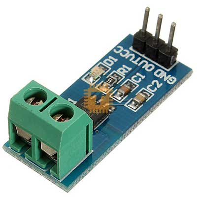
The ACS712 20A is a hall-effect-based linear current sensor designed for measuring high-current AC or DC loads. It provides a reliable and low-cost solution for power monitoring and control. By utilizing the Hall effect, the module ensures the high-current path is electrically isolated from your sensitive microcontroller electronics (like Arduino or ESP32), significantly increasing system safety.
Specifications
- Supply Voltage (VCC): 4.5V – 5.5V DC
- Measurement Range: -20A to +20A (Bi-directional)
- Sensitivity: 100mV/A
- Output Voltage at 0A: VCC / 2 (Typically 2.5V)
- Internal Conductor Resistance: 1.2 MOhm
- Isolation Voltage: 2.1 kVRMS
- Operating Temperature: -40C to +85C
Working Principle
As current passes through the copper conduction path inside the module, it generates a magnetic field. The integrated Hall-effect sensor detects this field and converts it into a voltage that is linearly proportional to the input current. Because the sensing is magnetic rather than direct, your measurement circuit remains isolated from the load circuit.
Features
- Bi-directional Measurement: Capable of measuring current in both directions. At 5V VCC, the output sits at 2.5V for 0A. It increases toward 5V for positive current (+20A = 4.5V) and decreases toward 0V for negative current (-20A = 0.5V).
- Galvanic Isolation: The 2.1 kVRMS isolation allows the sensor to be used in high-side applications safely, preventing high-voltage spikes from reaching the microcontroller.
- Low Power Loss: The extremely low resistance (1.2 MOhm of the internal copper path means the sensor introduces almost no voltage drop to your load, even at the full 20A capacity.
- High Bandwidth: Features an 80kHz bandwidth, allowing it to accurately sense fast-switching currents in motor controllers and SMPS.
- Stable Analog Output: The output is a simple DC voltage that maps directly to your MCU's Analog-to-Digital Converter (ADC).
Pin Configuration
- Input (Screw Terminals):
- Terminals: Connect in series with the positive or negative wire of the load you are measuring.
- Output (3-Pin Header):
- VCC: 5V Power Supply.
- OUT: Analog Signal Output.
- GND: Ground.
Common Applications
- Motor Speed Control: Monitoring the current draw of DC motors to prevent stalling or burnout.
- Solar Power Monitoring: Measuring the high-current output of large solar arrays.
- Inverter Systems: Tracking current in DC-to-AC power conversion.
- Industrial Automation: Detecting over-current faults in heavy-duty machinery.
Usage Tips
- Noise Management: If the reading is jumpy, add a small 0.1uF capacitor between the OUT pin and GND to filter out high-frequency noise.
- Zero-Current Calibration: Because the sensor is sensitive to external magnetic fields, it is best to take a reading at start-up (with the load off) to determine your specific 0A voltage baseline.
- Sensitivity Math: To calculate current in Amps for the 20A model: Current (A) = [Output Voltage (V) - (VCC / 2)] / 0.100
Sharing is caring, show love and share the product with your friends.
Featured


Add to Cart

Other Products

Add to Cart