1-Digit 7-Segment Red Colour 1.2 inch Common Cathode (DM0059) Products
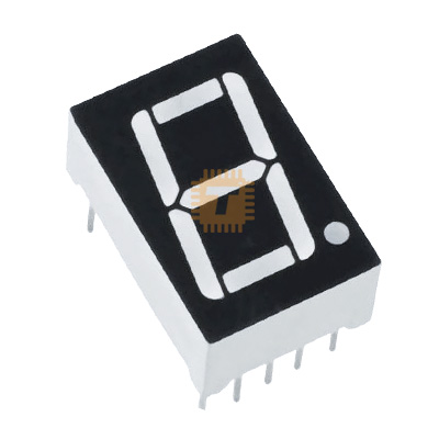
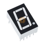
| Name | 1-Digit 7-Segment Red Colour 1.2 inch Common Cathode |
| Code | DM0059 |
| Price | Rs.150.00 |
| In Stock | Yes |
Product Details
The 1-Digit 7-Segment Red Colour 1.2-inch Common Cathode LED Display is a medium-format numerical display module engineered for clear, long-distance visual readouts in industrial, commercial, and instrumentation equipment. Featuring a 1.20-inch (30.48mm) character height with bright red GaAsP/GaP LED illumination, this display integrates two internal LED dies wired in series per segment (with a single die for the Decimal Point) to provide uniform brightness, crisp character definition, and wide viewing angles up to 25 to 30 meters. Encapsulated in a rugged epoxy resin package with a high-contrast black face and white diffused segment bars, the common cathode configuration ties all negative LED terminals together to a shared ground/negative pin while individual segments (A through G and Decimal Point) are driven via high-side source drivers or standard microcontroller driver stages. It is widely used in electronic weighing scales, process indicators, queue counters, digital timers, and power supply panel meters.
Specifications
- Part Number / Model: 12011BS / 12011BR / 12011B (Standard 1.2-inch 1-Digit 7-Segment Series)
- Display Type: 1-Digit 7-Segment Numerical LED Display with Right-Hand Decimal Point (DP)
- Digit Height: 1.20 Inch (30.48 mm)
- Module Dimensions: 40.6 mm (Height) × 28.8 mm (Width) × 10.0 mm (Thickness) ±0.5 mm
- Circuit Polarity: Common Cathode (CC - Shared Negative / Ground Rail)
- Emitted Light Color: High-Efficiency Super Red
- Dominant Wavelength (λd): 630 nm to 640 nm (Peak Wavelength λp ≈ 650 nm to 660 nm)
- Die Configuration per Segment: 2 LED dies in series per segment (A–G); 1 LED die for Decimal Point (DP)
- Forward Voltage Drop per Segment (VF - Segments A to G): Typ. 3.6V to 4.0V / Max. 4.8V (at IF = 20mA)
- Forward Voltage Drop for Decimal Point (VF - DP): Typ. 1.8V to 2.0V / Max. 2.4V (at IF = 20mA)
- Continuous Forward Current per Segment (IF): 20 mA (Continuous) / Max. 30 mA
- Peak Pulse Forward Current (IFP): Up to 100 mA (Duty ratio 1/10, 0.1ms pulse width)
- Reverse Breakdown Voltage per Segment (VR): 10V (Segments A–G) / 5V (DP)
- Luminous Intensity (Iv): 30 mcd to 60 mcd per segment (at IF = 20mA)
- Face & Segment Color: Black Surface Face with White Diffused Translucent Segment Lenses
- Power Dissipation per Segment (Pd): Up to 120 mW (Segments A–G) / 60 mW (DP)
- Operating Ambient Temperature (Topr): -25°C to +85°C
- Storage Temperature Range (Tstg): -30°C to +85°C
- Pinout Configuration: Standard 10-Pin Through-Hole DIP Header (Common Cathode pins typically on Pin 3 and Pin 8; Segments A: Pin 7, B: Pin 6, C: Pin 4, D: Pin 2, E: Pin 1, F: Pin 9, G: Pin 10, DP: Pin 5)
Features
- 1.20-Inch Medium-Large Digit Height: Delivers superior readability and visibility from across a room or workshop compared to standard 0.56-inch displays.
- Uniform High-Efficiency Red Emission: Matched dual-die series design ensures consistent illumination and solid bar geometry with no dark spots across segments A through G.
- Common Cathode Architecture: Simplifies interfacing with standard high-side source driver ICs (e.g., UDN2981 / MIC2981), 74HC595 shift registers with boosting buffers, or direct drive from 5V logic controllers.
- High-Contrast Matte Black Face: High optical contrast against milky-white diffused epoxy lenses ensures sharp segment definition under bright indoor lighting.
- Rugged DIP Footprint: Standard 10-pin DIP layout fits seamlessly into prototype breadboards, stripboards, and PCB through-hole sockets.
Common Applications
- Digital Weighing Scales & Balances: Commercial retail scales, luggage scales, and industrial floor scales.
- Process Control & Industrial Timers: Temperature meters, tachometers, pressure readouts, and batch counters.
- Laboratory & Bench Power Supplies: Real-time DC voltage and current readouts on benchtop equipment.
- Sports Scoreboards & Gym Timers: Lap timers, countdown clocks, and scoreboard displays.
- Queue & Ticket Callout Panels: Counter status indicators and token numbering displays.
Usage Tips
- Supply Voltage Consideration (+5V Rail Recommended): Because Segments A–G contain 2 LED dies in series requiring a forward voltage drop of approx. 3.6V to 4.0V, driving them directly from a 3.3V supply rail will result in extremely dim or unlit segments. Use a regulated +5V DC power source.
- Different Resistor Sizing for DP: The Decimal Point (DP) uses only 1 single LED die (VF ≈ 1.8V to 2.0V) compared to the dual-die segments A–G (VF ≈ 3.8V). Always calculate a higher series resistance for the DP pin to balance optical brightness and prevent overdriving the single DP die.
- Series Resistor Calculation Formula (from +5V at 15mA):
- Segments A–G: R_seg = (Vsupply - VF_seg) / IF = (5.0V - 3.8V) / 0.015A ≈ 80Ω to 82Ω (1/8W or 1/4W resistor).
- Decimal Point (DP): R_dp = (Vsupply - VF_dp) / IF = (5.0V - 2.0V) / 0.015A ≈ 200Ω to 220Ω (1/8W or 1/4W resistor).
- High-Side Drive Circuits: When multiplexing multiple digits, use high-side driver ICs like the **UDN2981 / MIC2981** or P-channel MOSFET / PNP transistor arrays to switch the segment anodes while switching the Common Cathode pins to ground via NPN / N-channel MOSFETs.
- Verify Pin 3 & Pin 8 Common Ground: Ensure both common cathode pins (Pin 3 and Pin 8) are tied securely to the system ground to properly sink return currents when all segments are illuminated (up to ~140mA total continuous current).
Sharing is caring, show love and share the product with your friends.
Featured

Add to Cart

Add to Cart

Other Products
Add to Cart