ACS712 30A Current Sensor Module for Arduino (MD0201) Products


We are sorry but the product is out of stock, please check back after few days.
| Name | ACS712 30A Current Sensor Module for Arduino |
| Code | MD0201 |
| Price | Rs.380.00 |
| In Stock | No |
| Package | MODULE |
Product Details
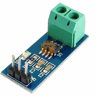
The ACS712 30A is a high-capacity Hall-effect-based linear current sensor designed for measuring substantial AC or DC loads. It is the most powerful variant in the ACS712 family, capable of handling up to 30 Amperes. By utilizing magnetic field sensing, it provides a safe, isolated interface between high-power circuits and low-voltage microcontrollers like Arduino, ESP32, or Raspberry Pi.
Specifications
- Supply Voltage (VCC): 4.5V – 5.5V DC
- Measurement Range: -30A to +30A (Bi-directional)
- Sensitivity: 66mV/A
- Output Voltage at 0A: VCC / 2 (Typically 2.5V)
- Internal Conductor Resistance: 1.2 MOhm
- Isolation Voltage: 2.1 kVRMS
- Operating Temperature: -40C to +85C
Working Principle
As current passes through the internal copper conduction path, it generates a magnetic field. The integrated Hall-effect sensor within the IC detects this field and converts it into a voltage that is linearly proportional to the current. This magnetic coupling ensures that your measurement electronics are physically and electrically isolated from the load being measured.
Features
- High-Capacity Bi-directional Sensing: Measures current in both directions. At a 5V supply, the output sits at 2.5V for 0A. It swings up toward 4.48V for +30A and down toward 0.52V for -30A.
- Total Electrical Isolation: The 2.1 kVRMS isolation rating allows you to monitor high-voltage lines (up to the rated isolation) without risking damage to your microcontroller.
- Extremely Low Power Loss: The internal resistance of the copper path is only 1.2 MOhm, ensuring that the sensor does not overheat or cause significant voltage drops in your high-current circuit.
- 80kHz Bandwidth: The fast response time makes it ideal for monitoring rapidly changing loads, such as those found in switching power supplies or motor drives.
- Analog Simplicity: The output is a linear DC voltage, making it easy to read using a single Analog-to-Digital Converter (ADC) pin.
Pin Configuration
- Input (Screw Terminals):
- Terminals: Connect in series with the load. Note: Due to the 30A rating, ensure you use appropriately thick wire (e.g., 10-12 AWG) to prevent the wires themselves from overheating.
- Output (3-Pin Header):
- VCC: 5V Power Supply.
- OUT: Analog Signal Output.
- GND: Ground.
Common Applications
- High-Power Motor Control: Monitoring large DC motors in robotics or industrial machinery.
- Renewable Energy: Tracking the output of high-wattage solar arrays or wind turbines.
- Inverters and UPS: Measuring current flow in heavy-duty power backup systems.
- Welding Equipment: Monitoring current in DIY spot welders or plasma cutters.
Usage Tips
- Thermal Management: While the sensor can handle 30A, the PCB traces and screw terminals may get warm during continuous high-load operation. Ensure there is adequate airflow around the module.
- Zero-Offset Calibration: Like all Hall-effect sensors, it can be influenced by Earth's magnetic field or nearby transformers. Always perform a "zero-current" calibration in your software to find the exact 2.5V (0A) baseline.
- Sensitivity Math: To calculate current in Amps for the 30A model: Current (A) = [Output Voltage (V) - (VCC / 2)] / 0.066
Sharing is caring, show love and share the product with your friends.
Featured

Add to Cart


Other Products

Add to Cart
Add to Cart
