
BFD-1000 5-Bit Line Tracking Sensor Module with IR Obstacle Sensor and Limit Switch (MD0577) Products
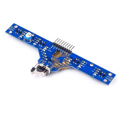
| Name | BFD-1000 5-Bit Line Tracking Sensor Module with IR Obstacle Sensor and Limit Switch |
| Code | MD0577 |
| Price | Rs.550.00 |
| In Stock | Yes |
| Package | MODULE |
Product Details
The BFD-1000 5-Bit Line Tracking Sensor Module is an all-in-one navigation and safety board designed for mobile robotics, line-following buggies, and autonomous automated guided vehicles (AGVs). It integrates seven independent sensing channels onto a single PCB: a 5-channel high-sensitivity infrared reflection array for line following, an adjustable front-facing IR obstacle avoidance sensor, and a front bumper micro limit switch for physical collision detection. Delivering standard digital logic levels across all channels, it connects directly to microcontrollers without requiring external comparator circuits.
Specifications
- Line Tracking Array: 5-channel high-sensitivity infrared reflection pairs
- Line Tracking Detection Range: 0 to 4 cm (Optimized for black-and-white surface contrast)
- Obstacle Detection Sensor: 1x forward-facing IR obstacle avoidance sensor
- Obstacle Detection Range: 0 to 5 cm (Adjustable via onboard trim potentiometer)
- Collision Detection: 1x front mechanical bumper micro switch (Touch/bump sensor)
- Operating Voltage: 3.0V to 5.5V DC (Compatible with 3.3V and 5V MCU logic)
- Output Format: Digital logic output (High/Low levels per channel)
- Status Indicators: Independent onboard indicator LEDs for each individual sensing channel
- Mounting: Multiple pre-drilled M3 mounting holes for rigid chassis attachment
Pinout and Interface Guide
- VCC: Power Supply Input (3.0V to 5.5V DC)
- GND: Common System Ground Reference
- SS1 to SS5: Digital Outputs for the 5 line-tracking IR sensors (Channels 1 through 5)
- Near / IR: Digital Output from the forward-facing IR obstacle distance sensor
- CLP / Bump: Digital Output from the physical micro limit switch (Bumper trigger)
Hardware and Operational Overview
- 5-Channel Ground Array: The five downward-pointing IR emitter/phototransistor pairs detect contrast differences between dark and light surfaces. When a sensor detects white (reflective), light bounces back and outputs one logic state; over a black line (non-reflective), the beam is absorbed and flips the digital output.
- Front Obstacle Sensor: Located at the front edge of the board, this sensor detects obstacles in the robot's immediate path before contact occurs. Detection threshold sensitivity is calibrated using the onboard multi-turn potentiometer.
- Mechanical Crash Bumper: The micro limit switch acts as a failsafe hardware collision sensor, instantly sending a digital interrupt or stop signal if an obstacle makes physical contact with the robot's chassis.
- Status LEDs: Seven onboard SMD LEDs provide real-time visual feedback for each line tracking bit, the forward distance sensor, and the limit switch, allowing rapid benchtop calibration without a serial terminal.
Key Features
- Integrated 7-in-1 Sensor Architecture: Consolidates line tracking, optical obstacle sensing, and physical impact detection on one board, simplifying wiring and reducing chassis clutter.
- Direct 3.3V and 5V Logic Compatibility: Operates reliably from 3.0V to 5.5V DC, interfacing directly with Arduino, ESP32, STM32, PIC, and Raspberry Pi GPIO pins.
- Independent Channel Calibration: High-sensitivity phototransistors provide reliable line edge detection for standard PID tracking algorithms, 90-degree cross-turns, and T-junctions.
- Clean Digital Outputs: Standard high/low output signals eliminate the need for analog-to-digital conversions, freeing up MCU processing cycles for motor control and steering algorithms.
Common Applications
- Line-Following Mobile Robots: Competition line followers, educational maze-solvers, and industrial Automated Guided Vehicles (AGVs).
- Grid and Junction Navigation: Tracking intersecting black or white grid patterns on warehouse and laboratory floors.
- Automated Obstacle Avoidance Platforms: Small robotics chassis requiring immediate collision detection and distance-based braking.
- STEM Robotics Education: Teaching basic digital logic reading, edge detection, and PID steering loops to robotics students.
Usage Tips
- Mounting Height: Mount the board so that the downward-facing line tracking sensors sit between 10 mm and 25 mm (1 to 2.5 cm) above the driving surface. Setting the board too high reduces signal contrast, while mounting it too low risks dragging over surface irregularities.
- Ambient Light Calibration: Calibrate the front obstacle sensor potentiometer under the ambient lighting of the actual operating environment, as strong halogen fixtures or direct sunlight can affect optical reflection thresholds.
- Line Width Recommendation: For optimal 5-bit tracking, use an electrical tape line width of 15 mm to 20 mm. This ensures that at least one or two center sensors remain active during straight-line travel while allowing the outer sensors to register sharp turns and deviations.
Sharing is caring, show love and share the product with your friends.
Featured

Add to Cart

Add to Cart

Add to Cart

Add to Cart
Other Products
Add to Cart

