KF128V 5.08mm Pitch 3-Pin Terminal Block (High Quality) PCB Mount (TB0062) Products
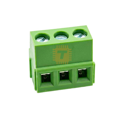
| Name | KF128V 5.08mm Pitch 3-Pin Terminal Block (High Quality) PCB Mount |
| Code | TB0062 |
| Price | Rs.50.00 |
| In Stock | Yes |
| Package | THT |
Product Details
The KF128V 5.08mm Pitch 3-Pin Terminal Block (High Quality) PCB Mount is a heavy-duty, vertical-entry screw-clamp wire-to-board connector engineered for robust, high-reliability field connections on printed circuit boards. Featuring standard 5.08mm (0.2-inch) pin pitch, it employs top-entry clamping with straight vertical (180°) wire insertion, making it the ideal solution for dense enclosures where horizontal wire entry is blocked by tall electrolytic capacitors, heat sinks, or chassis walls. Built with a reinforced phosphor bronze / brass rising clamp mechanism, corrosion-resistant tinned copper alloy solder pins, and an impact-resistant flame-retardant polyamide (PA66) housing with interlocking dovetail rails, this high-quality connector guarantees minimal contact resistance, superior pull-out retention, and dependable high-current power distribution for industrial automation, motor drives, and mains-switching hardware.
Specifications
- Connector Series / Model: KF128V (Vertical Wire Entry Type)
- Quality Grade: High Quality (Heavy-duty brass rising cage clamp & premium PA66 housing)
- Pin Pitch / Terminal Spacing: 5.08 mm (0.20 Inches)
- Number of Poles / Positions: 3 Pins (3-Way / 3-Pole)
- Wire Entry Orientation: Vertical (180° Top-Entry relative to PCB surface)
- Rated Operating Voltage: 300 V AC / DC
- Rated Current Capacity: 15 A to 20 A Max.
- Dielectric Withstanding Voltage: 2000 V AC for 1 minute
- Insulation Resistance: ≥ 5000 MΩ (at 500 V DC)
- Contact Resistance: ≤ 15 mΩ (High-conductivity, low-loss terminal interface)
- Compatible Wire Gauge: 24 AWG to 12 AWG (0.5 mm² to 2.5 mm² solid or stranded wire)
- Wire Strip Length: 6.0 mm to 7.0 mm
- Screw Fastener Type: M2.5 Metric Precision Slotted / Phillips Steel Screws (Zinc-plated / nickel-plated)
- Tightening Torque: Approx. 0.5 N·m (4.4 lbf·in)
- Internal Clamp / Cage Material: High-Tensile Brass / Phosphor Bronze (Non-shearing rising clamp design)
- Solder Pin Terminal Material: Tinned High-Conductivity Copper Alloy
- Solder Pin Dimensions: Approx. 0.8 mm × 1.0 mm (Recommended PCB drill hole: 1.3 mm to 1.5 mm)
- Insulating Body Material: Polyamide 66 (PA66, UL 94V-0 Flame Retardant, Industrial Green)
- Modular Assembly: Side Interlocking Dovetail Grooves (Expandable into custom multi-pole arrays)
- Operating Ambient Temperature: -40°C to +105°C
- Overall Dimensions: Approx. 15.24 mm × 10.0 mm × 14.0 mm (L × W × H excluding solder pins)
- Net Weight: Approx. 4.5 g to 5.8 g per piece
Features
- Vertical Top-Entry Cable Alignment: Accommodates perpendicular wire runs dropping directly onto the PCB, eliminating horizontal cable bending stress in cramped equipment chassis and DIN rail housings.
- Rising Cage Clamp Mechanism: High-grade brass rising cage lifts smoothly to trap wire conductors securely across a broad contact area, avoiding strand cutting or gouging during torque application.
- Modular Dovetail Interlock System: Side tongue-and-groove rails allow multiple 2-pin and 3-pin blocks to be combined into custom 6-pin, 9-pin, or continuous terminal strips while preserving 5.08mm center-to-center pitch.
- UL 94V-0 Flame-Retardant PA66 Body: Ruggedized engineering nylon shell provides high dielectric isolation, resists wave soldering heat, and withstands harsh industrial operating temperatures without embrittlement.
- Heavy Tin-Plated Terminals: Solder pins feature thick tin plating over a copper alloy core, promoting fast capillary solder wetting and preventing long-term galvanic corrosion in high-humidity environments.
Common Applications
- Mains AC Relay Modules: Terminating Live, Neutral, and Earth/Ground lines or 3-terminal SPDT relay contact connections (Normally Open, Common, Normally Closed).
- 3-Phase & Stepper Motor Drives: Interfacing brushless DC (BLDC) motor phase leads (U, V, W) and high-current stepper coil wires on CNC and 3D printer controller boards.
- Industrial Power Supplies: High-current terminals for Dual-Rail DC supplies (+V, GND, -V) or auxiliary battery-backup charging circuits.
- Analog & Digital Sensor Busses: Heavy-duty field terminal connections for 3-wire industrial transducers and telemetry transmitters (VCC, 4–20mA / 0–10V Signal, Ground).
- Solar & Renewable Energy Hubs: Connecting solar PV panels, charge controllers, and battery bank balance feeds in off-grid power systems.
Usage Tips
- Proper Screw Torquing:
- Tighten the M2.5 clamping screws to a recommended torque of 0.4 N·m to 0.5 N·m.
- Use an appropriately sized screwdriver bit (#1 Phillips or 3.0mm flat blade). Avoid over-torquing beyond rated specifications to prevent stress fractures on the PCB solder pads.
- Wire Stripping & Ferrule Recommendations:
- Strip wire insulation cleanly to 6.0 mm to 7.0 mm. Stripping too short may result in the clamp biting into the insulation jacket rather than bare conductor.
- For flexible, multi-stranded copper wire, crimp an insulated bootlace ferrule onto the wire end to prevent stray copper strands from causing inter-pin short circuits.
- PCB Pad & Hole Layout:
- Drill PCB through-holes to 1.3 mm to 1.5 mm in diameter with wide annular copper rings.
- Sufficient solder pad surface area provides necessary mechanical anchorage against the rotational torque applied when field wires are tightened down.
- Soldering Temperature & Dwell Time: Solder pins at 330°C to 350°C for approximately 2 to 3 seconds per pin using quality leaded or lead-free solder wire to establish shiny, complete 360° solder fillets on both sides of the board.
- Modular Gang Pre-Assembly: When chaining blocks together using the side dovetails, assemble the complete multi-pole row before inserting and soldering the pins into the circuit board to avoid mechanical pin misalignment and solder joint shear stress.
Sharing is caring, show love and share the product with your friends.
Featured


Add to Cart

Add to Cart

Other Products

Add to Cart