KF128V 5.08mm Pitch 3-Pin Terminal Block (Normal Quality) PCB Mount (TB0060) Products
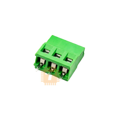
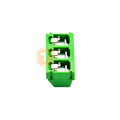

| Name | KF128V 5.08mm Pitch 3-Pin Terminal Block (Normal Quality) PCB Mount |
| Code | TB0060 |
| Price | Rs.30.00 |
| In Stock | Yes |
| Package | THT |
Product Details
The KF128V 5.08mm Pitch 3-Pin Terminal Block (Normal Quality) PCB Mount is a vertical-entry screw-clamp wire-to-board interconnect designed for reliable, solderless field wiring on printed circuit boards. Utilizing standard 5.08mm (0.2-inch) pin spacing, it features top-entry screw clamping with vertical (straight) wire insertion, allowing technicians to secure solid or stranded wire conductors directly to PCB power rails and signal lines. Built with an interlocking side-dovetail housing molded from flame-retardant thermoplastic and tinned through-hole solder pins, it provides a cost-effective, reusable wiring solution for general-purpose power distribution boards, relay driver modules, motor control shields, and educational electronics projects.
Specifications
- Connector Series / Model: KF128V (Vertical Wire Entry Type)
- Pin Pitch / Terminal Spacing: 5.08 mm (0.20 Inches)
- Number of Poles / Positions: 3 Pins (3-Way / 3-Pole)
- Wire Entry Orientation: Vertical (180° Top-Entry relative to PCB surface)
- Rated Operating Voltage: 300 V AC / DC
- Rated Current Capacity: 10 A to 15 A Max.
- Withstanding Voltage: 1500 V AC for 1 minute
- Insulation Resistance: ≥ 5000 MΩ (at 500 V DC)
- Contact Resistance: ≤ 20 mΩ
- Compatible Wire Gauge: 24 AWG to 12 AWG (0.5 mm² to 2.5 mm² solid or stranded wire)
- Wire Strip Length: 5.0 mm to 6.0 mm
- Screw Thread / Fastener Type: M2.5 Metric Slotted / Cross-Head Steel Screws (Zinc-plated)
- Tightening Torque: Approx. 0.4 N·m to 0.5 N·m (3.5 to 4.4 lbf·in)
- Pin Terminal Material: Tinned Brass / Phosphor Bronze Solder Pins (Through-Hole Mount)
- Solder Pin Dimensions: Approx. 0.8 mm × 1.0 mm (Recommended PCB hole diameter: 1.2 mm to 1.4 mm)
- Insulating Body Material: Flame-Retardant Polyamide / PBT (UL 94V-0 Rated, Green)
- Modular Assembly: Side Interlocking Dovetail Grooves (Expandable into custom multi-pole blocks)
- Operating Ambient Temperature: -40°C to +105°C
- Overall Dimensions: Approx. 15.24 mm × 10.0 mm × 14.0 mm (L × W × H excluding solder pins)
- Net Weight: Approx. 3.5 g to 5.0 g per piece
Features
- Vertical Top-Entry Architecture: Facilitates straight vertical wire drops into tight PCB enclosures where horizontal side-entry cabling is obstructed by heat sinks, relays, or chassis walls.
- Modular Dovetail Interlock Design: Molded side tongue-and-groove rails allow users to snap multiple 2-pin or 3-pin blocks together into 6-pin, 9-pin, or custom length arrays with uniform 5.08mm pitch alignment.
- Standard Industrial Pitch: Compatible with standard 5.08mm through-hole footprints, perfboards, and prototyping shields, eliminating the need for custom PCB layout geometries.
- High-Retention Screw-Clamp Contacts: Clamps solid or stranded wire ends firmly against the internal conductor plate, preventing loose wire pullouts under light mechanical vibration.
- Flame-Retardant Insulating Shell: Tough engineering thermoplastic prevents adjacent-pin arcing, withstands standard soldering heat, and provides electrical isolation across high-voltage AC/DC lines.
Common Applications
- Power Supply Distribution: Securing main 12V/24V DC input rails and multi-tap ground returns to custom bench power supplies and breakout boards.
- Relay & Solenoid Modules: Interfacing high-voltage AC mains (NO/COM/NC contacts) to external lamps, water pump motors, and home automation relays.
- Motor Driver Carrier Boards: Connecting DC motor, stepper motor phase, and high-current driver outputs on 3D printer mainboards and CNC controllers.
- Industrial Sensor Busses: Terminating 3-wire analog/digital sensor lines (VCC, Signal, GND) on PLC expansion boards and telemetry hubs.
- Educational STEM & Prototyping: Reusable screw-down connection points for DIY microcontrollers, solar charging controllers, and audio amplifier kits.
Usage Tips
- Proper Screw Torquing (CRITICAL):
- As a standard commercial-grade terminal block, avoid applying excessive force when tightening the M2.5 screws.
- Over-torquing (>0.5 N·m) can strip the internal brass threading or distort the clamp cage, resulting in loose terminal contact and intermittent power delivery. Tighten firmly until snug without forcing the screw past its natural stop.
- Wire Stripping & Stranded Wire Prep:
- Strip wire insulation cleanly to 5.0 mm to 6.0 mm. If stripped too short, the screw clamp will bite down onto the insulation rather than bare conductor, causing an open circuit.
- When using finely stranded wire, twist the strands tightly and lightly tin the tip with solder, or crimp a matching bootlace ferrule over the end to prevent stray wire whiskers from bridging to adjacent pins.
- PCB Solder Hole Sizing: Design or drill PCB through-holes to an internal diameter of 1.2 mm to 1.4 mm with broad copper annular rings. Generous solder pad copper ensures mechanical rigidity against leverage forces applied when screwing down external wires.
- Soldering Iron Temperature: Solder pins at 330°C to 350°C for approximately 2 to 3 seconds per pin. Prolonged iron contact (>5 seconds) can soften the plastic base, misaligning the internal terminal structure before cooling.
- Modular Assembly Sequence: If ganging multiple blocks together using the side dovetails, slide them together before inserting and soldering the pins into the PCB to ensure straight, stress-free pin alignment across the row.
Sharing is caring, show love and share the product with your friends.
Featured
Add to Cart


Other Products
Add to Cart
Add to Cart
Add to Cart