
LiFePO4 4S 14.4V 100A BMS Battery Protection Board (MD0769) Products
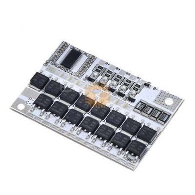
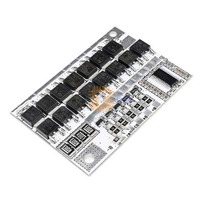
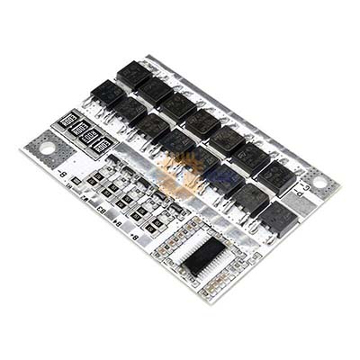
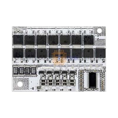
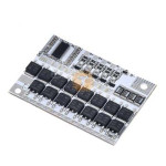
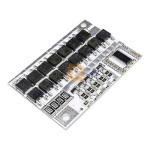
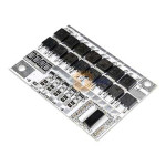
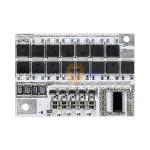
| Name | LiFePO4 4S 14.4V 100A BMS Battery Protection Board |
| Code | MD0769 |
| Price | Rs.850.00 |
| In Stock | Yes |
| Package | MODULE |
Product Details
The LiFePO4 4S 14.4V 100A BMS Battery Protection Board is a heavy-duty battery management system designed for 4-series Lithium Iron Phosphate (LiFePO4) battery packs. Built with high-current MOSFETs, integrated passive balancing circuitry, and onboard thermal monitoring, it provides comprehensive hardware-level protection against overcharge, deep over-discharge, short-circuit, and overcurrent conditions. It is engineered to maintain cell balance, extend battery cycle life, and ensure safe operation in solar energy storage, inverter systems, electric vehicles, and high-demand 12V/14.4V power banks.
Specifications
- Battery Chemistry: Lithium Iron Phosphate (LiFePO4) only
- Cell Configuration: 4S (4 cells in series)
- Nominal Pack Voltage: 12.8V (3.2V per cell)
- Full Charge Voltage: 14.4V to 14.6V (3.6V to 3.65V per cell)
- Continuous Discharge Current:
- Separate Port Configuration: Up to 80A
- Same Port (Common Port) Configuration: Up to 60A
- Continuous Charging Current: Up to 60A
- Peak / Overcurrent Protection: 100A (Overcharge and Over-discharge current threshold)
- Over-Discharge Current Protection Delay: 0.5 to 1.5 seconds
- Overcharge Protection (Per Cell):
- Trigger Voltage: 3.61V to 3.69V
- Protection Delay: 1.5 to 2.5 seconds
- Release / Recovery Voltage: 3.50V to 3.60V
- Over-Discharge Protection (Per Cell):
- Trigger Voltage: 2.27V to 2.43V
- Release / Recovery Voltage: 2.45V to 2.65V
- Cell Balancing:
- Balance Activation Threshold: 3.355V to 3.455V per cell
- Balance Current: ~50mA passive bleed current
- Short-Circuit Protection:
- Trigger Delay: 100 to 600 microseconds
- Recovery Condition: Cut load / disconnect load to auto-recover
- Temperature Protection: Integrated NTC temperature sensor interface
- Wire Break / Disconnection Protection: Supported (Automatic shutdown if a balance sense lead disconnects)
Terminal and Wiring Guide
- High-Current Power Solder Pads:
- B-: Connects to the main negative terminal of the 4S battery pack.
- P-: Load negative output (for common port setups) or discharge negative terminal.
- C-: Charge negative terminal (for separate port charging configurations).
- Multi-Pin Balance Sensing Harness (5-Pin Connector):
- B- (Black): Connect to Cell 1 Negative (Main Battery Pack Ground).
- B1 (White / First Sense Wire): Connect to junction between Cell 1 Positive and Cell 2 Negative (+3.2V nominal).
- B2 (White / Second Sense Wire): Connect to junction between Cell 2 Positive and Cell 3 Negative (+6.4V nominal).
- B3 (White / Third Sense Wire): Connect to junction between Cell 3 Positive and Cell 4 Negative (+9.6V nominal).
- B+ (Red / Fourth Sense Wire): Connect to Cell 4 Positive (Main Battery Pack Positive, +12.8V nominal).
- NTC Interface: Connects an external NTC thermistor probe placed between cells to guard against over-temperature conditions.
Key Features
- Comprehensive Battery Protection: Independent hardware IC protects against cell-level overcharging, deep discharge, high-current short circuits, and cell sense wire disconnection.
- Passive Cell Balancing: Onboard 50mA shunt resistors bleed excess charge from higher-voltage cells once they surpass 3.355V–3.455V, ensuring all four cells top out evenly.
- Rapid Short-Circuit Response: Shuts down output within 100 to 600 microseconds during a short-circuit event, automatically resetting once the fault load is disconnected.
- High Heat Dissipation: Features an aluminium heat spreader over the low-resistance power MOSFET bank to manage heat under sustained discharge loads.
- Flexible Port Routing: Supports both separate-port (higher discharge rating) and common-port wiring topologies depending on system requirements.
Common Applications
- 12V Lead-Acid Replacement: Upgrading SLA/AGM batteries to 12.8V LiFePO4 in UPS backups, recreational vehicles (RVs), marine boats, and trolling motors.
- Off-Grid Solar Energy Storage: Managing 12V 50Ah to 200Ah residential solar battery banks with dedicated MPPT or PWM charge controllers.
- High-Power Portable Power Stations: Driving DC-to-AC power inverters, portable camping power boxes, and high-intensity field equipment.
- Automotive Audio & Auxiliary Power: Providing high burst current for auxiliary automotive sound amplifiers and mobile lighting rigs.
Installation and Wiring Sequence
- Cell Matching: Verify that all four LiFePO4 cells are top-balanced and matched in voltage (within 0.05V of each other) and internal resistance before assembling the pack.
- Wire Main Negative: Solder a thick high-gauge wire (8 AWG to 10 AWG) from the pack's main negative terminal to the B- pad on the BMS board.
- Assemble the Balance Harness: Wire the balance harness leads starting from B- up to B+ across the cell terminals. Do not plug the balance harness into the BMS yet.
- Harness Voltage Verification: Use a digital multimeter to measure voltages between adjacent pins on the unplugged connector:
- Pin 1 (B-) to Pin 2 (B1): ~3.2V to 3.6V
- Pin 2 (B1) to Pin 3 (B2): ~3.2V to 3.6V
- Pin 3 (B2) to Pin 4 (B3): ~3.2V to 3.6V
- Pin 4 (B3) to Pin 5 (B+): ~3.2V to 3.6V
- Connect Harness: Plug the verified balance connector firmly into the BMS socket.
- Connect Output Lines: Solder the load and charge negative leads to P- and/or C-. The main positive load terminal connects directly to the pack's main B+ terminal.
Usage Tips
- Strict Chemistry Compatibility: This BMS is specifically calibrated for LiFePO4 (3.2V nominal, 3.65V peak). Do not use this board with standard Li-ion or LiPo cells (3.7V nominal, 4.2V peak), as the lower cut-off thresholds will cause severe undercharging and cell imbalance.
- Cable Sizing: When drawing continuous currents above 40A, use short, heavy-gauge multi-strand silicone wiring (8 AWG to 10 AWG) soldered with adequate heat to avoid cold joints and resistive heating.
- Initial Activation: If there is no voltage reading across B+ and P- after assembly, connect a 14.4V–14.6V LiFePO4 battery charger across B+ and P- (or C-) for 2 to 3 seconds to release the BMS sleep/protection lockout.
Sharing is caring, show love and share the product with your friends.
Featured

Add to Cart
Add to Cart

Other Products
Add to Cart
