MPU9250 9-DOF 3-Axis Acceleration Gyroscope Magnetometer (MD0404) Products

| Name | MPU9250 9-DOF 3-Axis Acceleration Gyroscope Magnetometer |
| Code | MD0404 |
| Price | Rs.750.00 |
| In Stock | Yes |
| Package | MODULE |
Product Details
** ITEM DISCONTINUED BY THE MANUFACTURER **
NOTE: Some modules are known to have a non-functioning magnetometer. In such cases, please use a separate magnetometer module such as the one below.
HSCDTD008A 3 Axis Compass Magnetometer Module
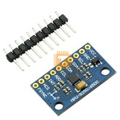
The MPU9250 is a high-performance 9-axis motion tracking sensor that integrates a 3-axis accelerometer, 3-axis gyroscope, and 3-axis magnetometer into a single compact package. Designed for embedded systems, robotics, and wearable applications, it offers precise inertial measurements and supports I2C and SPI communication protocols.
Specifications
- Sensor Type: 9-DOF MEMS motion tracking
- Accelerometer Range: Plus or minus 2g, 4g, 8g, 16g
- Gyroscope Range: Plus or minus 250, 500, 1000, 2000 degrees per second
- Magnetometer Range: Plus or minus 4800 micro-Teslas
- Accelerometer Resolution: 16384 LSB/g (at plus or minus 2g)
- Gyroscope Resolution: 131 LSB/degree/second (at plus or minus 250 degrees per second)
- Magnetometer Resolution: 0.6 micro-Teslas/LSB
- Interface: I2C (up to 400 kHz), SPI (up to 20 MHz)
- I2C Address: 0x68 (default), 0x69 (if AD0 pin is pulled high)
- Supply Voltage: 3.3V via onboard LDO (accepts 4.4V to 6.5V inputs safely)
- Temperature Sensor: Integrated onboard
Interface and Pinout Guide
- VCC: 4.4V to 6.5V Power Input (Onboard regulator provides 3.3V to the sensor)
- GND: Ground Reference
- SCL / SCLK: I2C Serial Clock / SPI Clock
- SDA / SDI: I2C Serial Data / SPI Master Out Slave In (MOSI)
- EDA: Auxiliary I2C Serial Data (for connecting external non-inertial sensors)
- ECL: Auxiliary I2C Serial Clock
- ADO / SDO: I2C Address Select / SPI Master In Slave Out (MISO)
- NCS: SPI Chip Select (Active Low, pull high for I2C mode)
- INT: Programmable Interrupt Pin
Key Features
- Complete 9-Axis Tracking: Combines an accelerometer, gyroscope, and magnetometer in one module to eliminate alignment errors common with separate boards.
- Onboard DMP: Built-in Digital Motion Processor handles complex sensor fusion calculations internally to offload processing from your microcontroller.
- Signal Stability: Includes an onboard voltage regulator to safely handle power inputs up to 6.5V.
- Integrated Resistors: Features built-in pull-up resistors on SDA, SCL, and nCS, alongside pull-down resistors on FSYNC and AD0.
- Broad Compatibility: Fully compatible with Arduino, STM32, ESP32, Raspberry Pi, and other popular microcontroller platforms.
- Versatile Use Cases: Ideal for mobile robotics, virtual reality or augmented reality input, gesture recognition systems, and motion logging devices.
Usage Tips
- Logic Level Translation Warning: While the board accepts a 5V power input via VCC, the data and clock logic pins (SDA, SCL, ADO, NCS, INT) operate strictly at 3.3V levels. If you connect this module to a development board with 5V TTL logic (such as an Arduino Uno or Mega), you must use a bidirectional logic level shifter on the communication lines. Connecting 5V logic signals directly can cause erratic readings, data corruption, or permanent damage to the sensor chip.
- Address Configuration: The default 7-bit I2C address is 0x68. If you have a second module on the same bus, connect the AD0 pin to VCC to change its address to 0x69.
- Magnetometer Mapping: The internal magnetometer is routed as a secondary device. Most standard software libraries automatically configure the auxiliary I2C bypass mode so your controller can access it directly.
- Calibration Step: To secure accurate heading data from the compass, the sensor must be calibrated in its final enclosure to cancel out local magnetic distortions caused by nearby battery packs or motor currents.
- Wiring Strain Relief: Ensure your connecting wires are flexible and securely routed, as high vibrations from robotic frames can introduce noise or cause the fragile header connections to break.
Arduino Library: MPU9250_asukiaaa
Reference tutorial: MPU9250 9-Axis Sensor Module
Sharing is caring, show love and share the product with your friends.
Featured


Add to Cart

Add to Cart

Add to Cart
Other Products


Add to Cart

