Multi-function Mini Boost Module Step Up Board 5/8/9/12V 1.5A (MD0745) Products
| Name | Multi-function Mini Boost Module Step Up Board 5/8/9/12V 1.5A |
| Code | MD0745 |
| Price | Rs.150.00 |
| In Stock | Yes |
| Package | MODULE |
Product Details
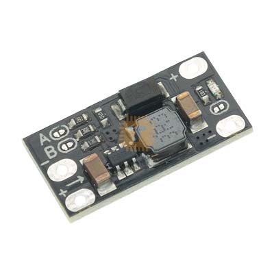
The Multi-function Mini Boost Board is an ultra-compact, highly efficient step-up DC-DC converter designed for tight electronic enclosures and battery-powered applications. Unlike traditional buck-boost modules that rely on bulky potentiometers, this board uses a clever hardwired solder-bridge jumper system to select between four fixed output voltages: 5V, 8V, 9V, or 12V. This makes it immune to mechanical vibration and ideal for small-scale drones, portable instruments, and microcontroller projects.
Specifications
- Module Type: Fixed-selectable non-isolated step-up (Boost) converter
- Selectable Output Voltages: 5V, 8V, 9V, and 12V DC (Default output configuration is 12V)
- Input Voltage Range: 2.5V to VOUT (The input voltage must remain lower than your chosen output voltage)
- Output Current Capabilities: Up to 1.5A maximum (Highly dependent on the input-to-output voltage delta)
- Quiescent Current (LED On): ~6mA at 12V output
- Quiescent Current (LED Off): <1mA>
- Form Factor: Miniature footprint for space-constrained builds
Voltage Selection Guide (Solder Pads A and B)
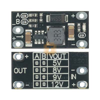
The front side of the PCB features two configurable solder pads labelled A and B. By bridging or opening these pads with a soldering iron, you instantly configure the fixed output rail:
- 5V Output: Pad A Disconnected (Open) / Pad B Disconnected (Open)
- 8V Output: Pad A Connected (Bridged) / Pad B Disconnected (Open)
- 9V Output: Pad A Disconnected (Open) / Pad B Connected (Bridged)
- 12V Output (Default): Pad A Connected (Bridged) / Pad B Connected (Bridged)
Interface and Wiring Points
- VIN+: Positive DC Voltage Input (2.5V up to the selected output voltage)
- GND: Common Ground input and output point
- VOUT+: Regulated DC Voltage Output (5V, 8V, 9V, or 12V based on solder configurations)
- Indicator Jumper: A tiny track beside the onboard LED indicator that can be sliced with a hobby knife to turn off the LED status light, cutting standby current draw down below 1mA.
Key Features
- Ultra-Reliable Jumper System: Eliminates the trimming potentiometer found on normal booster modules, preventing output voltage drifting caused by heavy structural vibrations or thermal shifts.
- Excellent Current-to-Size Ratio: Despite measuring less than a few centimeters square, the board safely manages currents up to 1.5A for driving power-hungry peripheral modules.
- Low-Power Standby Optimizations: Allows physical deactivation of the onboard power LED indicator, dropping standby consumption below 1mA to preserve battery health in long-term field logging nodes.
- Clean Logic Output: Provides steady, low-ripple power lines suitable for driving wireless transmitters, development controllers, and audio circuits.
Common Applications
- Lithium Battery Stepping: Boosting a single-cell 3.7V Lithium Polymer or 18650 battery directly up to a stable 5V or 9V rail to power microcontrollers and communication gear.
- Router Power Backups: Providing auxiliary 9V or 12V power backups for low-power network components during mains failures.
- RC Drone Electronics: Regulating power tracks for FPV video transmitters, camera modules, or auxiliary sensors demanding stable 9V/12V feeds.
- Portable Instruments: Creating steady power supplies within miniature custom handheld test equipment and multi-sensor configurations.
Usage Tips
- Boost Mode Restriction: This module cannot step down voltage. Your input voltage must always be strictly lower than the target output configuration. For example, if you set the board to a 5V output, running it with a 6V input will cause unregulated pass-through currents that can ruin downstream circuitry.
- Thermal Limitations: Running the board continuously at high current thresholds will cause rapid heat build-up due to its minimal surface area. For continuous operations exceeding 800mA, ensure adequate ventilation or attach a small silicone thermal pad underneath the module casing.
- Soldering Technique: Use a fine chisel or conical soldering tip when bridging pads A and B. Avoid applying excessive heat for longer than three seconds to prevent the tiny SMD copper solder pads from lifting off the fiberglass substrate.
Sharing is caring, show love and share the product with your friends.
Featured

Add to Cart

Add to Cart

Add to Cart

Add to Cart