
NodeMCU ESP32-S Dev Board MicroUSB 38-pin WiFi Bluetooth IoT (Narrow Board) (MD1046) Products
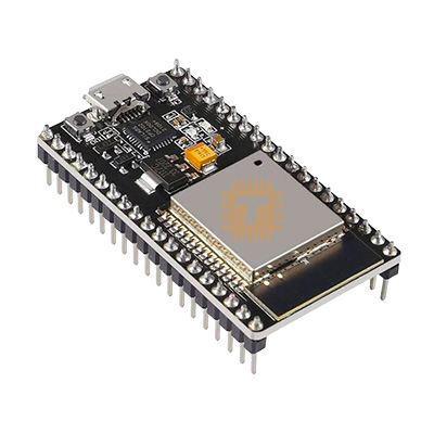
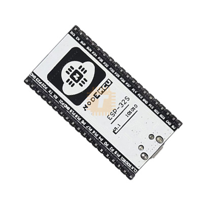
| Name | NodeMCU ESP32-S Dev Board MicroUSB 38-pin WiFi Bluetooth IoT (Narrow Board) |
| Code | MD1046 |
| Price | Rs.1,550.00 |
| In Stock | Yes |
| Package | MODULE |
Product Details
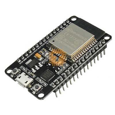
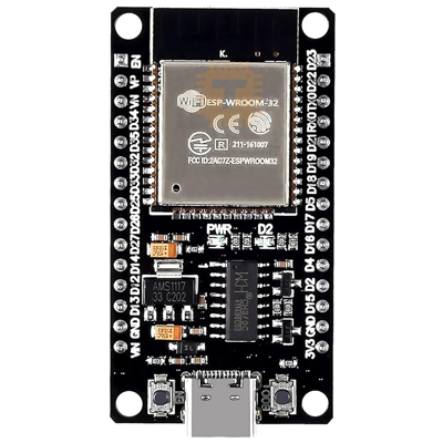
The NodeMCU ESP32-S 38-Pin Narrow Development Board (Micro-USB / Wi-Fi + Bluetooth + BLE) is a versatile, high-performance IoT development platform based on the Espressif ESP-WROOM-32 (ESP32-S) module. Powered by the dual-core 32-bit Xtensa LX6 microprocessor running at up to 240 MHz, it integrates 2.4 GHz Wi-Fi (802.11 b/g/n) and dual-mode Bluetooth (v4.2 BR/EDR and BLE). Designed in a slim, breadboard-friendly "Narrow" form factor, it leaves a full row of tie-points exposed on both sides of a standard solderless breadboard. Equipped with an onboard CP2102 USB-to-UART bridge, Micro-USB port, 3.3V low-dropout voltage regulator, and dual EN/BOOT buttons, it is widely used in smart home automation, industrial IoT telemetry, robotics, sensor nodes, and wireless edge computing.
Specifications
- Module Model: ESP-WROOM-32 / ESP32-S Module
- Core Processor: Dual-Core 32-bit Xtensa LX6 Microprocessor
- CPU Operating Frequency: Adjustable from 80 MHz up to 240 MHz (Up to 600 DMIPS)
- Internal SRAM: 520 KB
- Embedded Flash Memory: 4 MB (32 Mb) SPI Flash
- ROM: 448 KB (for booting and core functions)
- Board Form Factor: Narrow 38-Pin Breadboard-Friendly Layout (0.9-inch / 22.86mm row spacing)
- Wireless Connectivity:
- Wi-Fi: 802.11 b/g/n (up to 150 Mbps) with WEP, WPA/WPA2-PSK (AES/TKIP)
- Bluetooth: Bluetooth v4.2 BR/EDR and Bluetooth Low Energy (BLE)
- USB Interface & Bridge: Micro-USB Port with onboard Silicon Labs CP2102 USB-to-UART Bridge Controller
- Operating Supply Voltage:
- Via Micro-USB: 5.0V DC
- Via Vin Pin: 5.0V to 9.0V DC (Regulated down via onboard 3.3V LDO)
- Logic / Core Operating Voltage: 3.3V DC (Strictly 3.3V I/O logic levels)
- Onboard Voltage Regulator: 3.3V LDO Regulator (AMS1117-3.3 / ME6211 supporting up to 800mA peak)
- General Purpose I/O (GPIO): Up to 30 usable GPIO pins with multi-function multiplexing
- Hardware Peripherals & Interfaces:
- ADC: 12-bit SAR ADC up to 18 Channels (ADC1 and ADC2)
- DAC: 2x 8-bit Digital-to-Analog Converters (DAC1 - GPIO25, DAC2 - GPIO26)
- Capacitive Touch: 10x Capacitive Touch Sensing GPIO Channels
- PWM: Up to 16 independent hardware PWM channels (LEDC module)
- Serial UART: 3x Hardware UART interfaces (UART0, UART1, UART2)
- SPI: 3x SPI interfaces (SPI, HSPI, VSPI)
- I2C: 2x I2C interfaces (supporting master/slave modes)
- I2S / SDIO / CAN: 2x I2S interfaces, SDIO Host/Slave, CAN Bus 2.0B controller (TWAI)
- Onboard Controls & Indicators:
- Buttons: EN (Reset) Button and BOOT (GPIO0 Flash / Download) Button
- LED Indicators: Power LED (Red) and User / Test LED (Blue - connected to GPIO2)
- Antenna: Onboard PCB trace antenna (3D impedance matched)
- Operating Ambient Temperature: -40°C to +85°C
- Dimensions: Approx. 55 mm × 28 mm × 12 mm (L × W × H, including pin headers)
Features
- True Breadboard-Friendly Narrow Width: Engineered specifically with a compact row spacing that fits directly into standard 830-point / 400-point breadboards while leaving accessible pin columns on both sides for jumper wire hookups.
- Dual-Core 240MHz Computing Power: Dual 32-bit cores allow dedicated real-time Wi-Fi/Bluetooth stack management on one core while executing sensor parsing, algorithms, or FreeRTOS tasks on the other.
- Comprehensive Dual Wireless Radio: Combines high-bandwidth 2.4GHz Wi-Fi for cloud connectivity (MQTT, HTTP, WebSockets) and low-power BLE for smartphone pairing, beaconing, and local provisioning.
- Plug-and-Play USB Programming: Built-in CP2102 USB-to-UART converter with auto-download reset circuitry eliminates manual button pressing during Arduino IDE, ESP-IDF, or MicroPython sketch uploads.
- Rich Peripheral Set: Integrated 12-bit ADCs, dual 8-bit DACs, hardware PWM, touch sensors, and hardware crypto acceleration (AES, SHA-2, RSA, ECC).
Common Applications
- Smart Home & Building Automation: Wi-Fi smart switches, smart plugs, climate controllers, and Home Assistant / ESPHome nodes.
- Industrial IoT & Telemetry: Remote sensor datalogging, Modbus RTU-to-Wi-Fi bridges, and cloud-connected MQTT gateways.
- DIY Robotics & Motor Control: Bluetooth/Wi-Fi controlled rovers, drone flight controllers, and multi-channel servo robotic arms.
- Environmental & Weather Monitoring: Solar-powered weather stations with deep-sleep power saving and cloud dashboard integration.
- Audio & Voice Streaming: Web radio streaming, I2S DAC audio playback, and Bluetooth audio sink applications.
Usage Tips
- 3.3V Logic Level Safety: All GPIO pins operate at **3.3V DC logic levels and are NOT 5V tolerant**. When interfacing with 5V sensors or 5V microcontrollers (e.g., standard 5V Arduino boards), always use a bidirectional logic level shifter or resistor voltage divider.
- ADC2 Wi-Fi Conflict: ADC2 channels (GPIO0, 2, 4, 12, 13, 14, 15, 25, 26, 27) cannot be used for analog reading when Wi-Fi is actively transmitting. Always prioritize **ADC1 pins (GPIO32 to GPIO39)** for analog sensors when Wi-Fi functions are active.
- Input-Only Pins (GPI): GPIO34, GPIO35, GPIO36 (VP), and GPIO39 (VN) are **input-only pins**. They do not possess internal pull-up/pull-down resistors and cannot be configured as digital outputs.
- Power Supply Peak Current: During Wi-Fi calibration and transmission bursts, the ESP32 can draw transient current spikes up to 500mA. Use a stable 5V power supply rated for **at least 1.0A to 2.0A** to prevent brownout detector resets.
- Boot Strapping Pins: Avoid pulling GPIO0, GPIO2, GPIO12, or GPIO15 HIGH or LOW externally during startup, as they determine chip boot modes (flashing vs. SPI boot).
Sharing is caring, show love and share the product with your friends.
Featured


Add to Cart
Other Products

Add to Cart
Add to Cart

