Original GT50J325 600V 50A IGBT TO-3PL (DI0306) Products
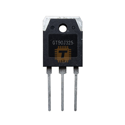
| Name | Original GT50J325 600V 50A IGBT TO-3PL |
| Code | DI0306 |
| Price | Rs.410.00 |
| In Stock | Yes |
| Package | TO-247 |
Product Details
The Original GT50J325 600V 50A IGBT is a 4th Generation N-channel Insulated Gate Bipolar Transistor manufactured by Toshiba. Encapsulated in a heavy-duty TO-3PL / TO-3P(LH) through-hole package, it integrates an ultra-fast recovery freewheeling diode (FRD) between the emitter and collector. Engineered for high-power, high-speed switching applications operating at frequencies up to 50 kHz, the GT50J325 delivers low collector-emitter saturation voltage (Vce(sat) = 2.0V typ.), fast fall times (tf = 0.05µs), and low total switching energy losses. It is widely used in high-frequency inverter welding machines, motor speed controllers, uninterruptible power supplies (UPS), and induction heating systems.
Specifications
- Part Number / Model: GT50J325 (Toshiba 4th Generation IGBT Series)
- Transistor Type: N-Channel Enhancement Mode IGBT with Integrated Fast Recovery Diode (FRD)
- Package Type: TO-247
- Collector-Emitter Voltage (Vces): 600V
- Gate-Emitter Voltage (Vges): ±20V DC
- Continuous Collector Current (Ic): 50A (DC at Tc = 25°C)
- Pulsed Collector Current (Icp): 100A (1ms pulse)
- Diode Continuous Forward Current (If): 50A (DC) / 100A (Pulsed 1ms)
- Collector-Emitter Saturation Voltage (Vce(sat)): Typ. 2.0V / Max. 2.45V (at Vge = 15V, Ic = 50A)
- Diode Forward Voltage Drop (Vf): Max. 4.2V (at If = 50A, Vge = 0V)
- Gate-Emitter Cut-Off / Threshold Voltage (Vge(off)): 3.5V to 6.5V (at Vce = 5V, Ic = 5mA)
- Turn-On Switching Loss (Eon): Typ. 1.30mJ
- Turn-Off Switching Loss (Eoff): Typ. 1.34mJ
- Fall Time (tf): Typ. 0.05µs (50ns) / Max. 0.15µs
- Turn-Off Time (toff): Typ. 0.43µs (430ns)
- Diode Reverse Recovery Time (trr): Typ. 65ns (at If = 50A, di/dt = -100A/µs)
- Collector Power Dissipation (Pc): 240W (at Tc = 25°C)
- Operating Junction Temperature (Tj): Up to +150°C
- Storage Temperature Range (Tstg): -55°C to +150°C
- Thermal Resistance, Junction to Case (Rth(j-c)): ~0.52°C/W
- Pinout Configuration: Pin 1: Gate (G), Pin 2: Collector (C), Pin 3: Emitter (E), Tab: Collector (C)
Features
- Toshiba 4th Generation Technology: Provides optimized carrier distribution for minimal conduction loss and fast turn-off switching characteristics.
- High-Speed 50kHz Operation: Fast 50ns fall time minimizes turn-off tail current, drastically lowering switching energy dissipation in high-frequency stages.
- Integrated Fast Recovery Diode (FRD): Built-in anti-parallel diode with 65ns recovery time protects against reverse inductive kickback and simplifies PCB layout.
- Low Conduction Saturation: Typical 2.0V Vce(sat) ensures high electrical efficiency and reduced thermal dissipation during heavy 50A continuous conduction.
- Heavy-Duty TO-3PL Metal Tab Package: Oversized copper backing tab provides superior thermal transfer (240W Pc rating) and rigid through-hole mechanical mounting.
Common Applications
- Inverter Arc & TIG Welding Machines: Primary and secondary bridge power switching stages for heavy-duty welding equipment.
- Induction Heating & Melting Systems: High-frequency resonant inverter switching in commercial cookers and industrial induction furnaces.
- Uninterruptible Power Supplies (UPS): DC-to-AC inversion stages and battery boost converters in online high-power UPS units.
- Industrial AC / DC Motor Drives: H-bridge switching and variable frequency drives (VFD) for industrial automation.
- High-Power Switch-Mode Power Supplies: Full-bridge and half-bridge DC-DC power converters.
Usage Tips
- Gate Drive Optimization: Drive with a standard +15V gate voltage to guarantee full saturation and achieve the lowest Vce(sat) rating; use 0V to -5V turn-off bias to prevent spurious Miller turn-on in noisy inverter bridges.
- Gate Damping Resistor: Place a series gate damping resistor (typically 10Ω to 20Ω, datasheet reference 13Ω) close to Pin 1 (Gate) to eliminate parasitic oscillation and limit turn-on current spikes.
- Thermal Management & Mounting: Mount the TO-3PL tab to a clean, flat aluminum/copper heatsink with high-conductivity thermal paste; use an insulating mica/silicone sheet and bushing if the heatsink is grounded.
- Snubber Protection: In high-current inductive switching circuits, place high-voltage, low-inductance film/ceramic snubber capacitors directly across the collector and emitter rails to suppress high-voltage turn-off spikes.
Sharing is caring, show love and share the product with your friends.
Featured


Add to Cart

Add to Cart