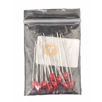
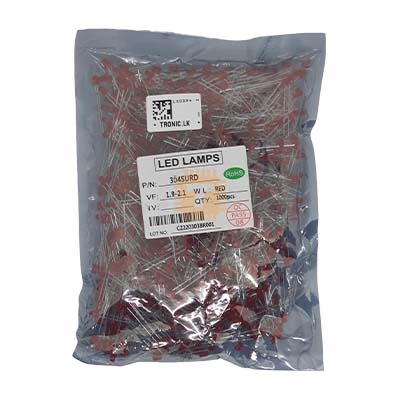
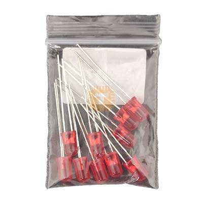
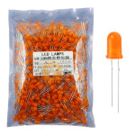
Original LED 5mm Orange Diffused Pack Production Quality (1000Pcs) (LE0147) Products
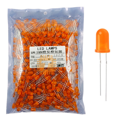
| Name | Original LED 5mm Orange Diffused Pack Production Quality (1000Pcs) |
| Code | LE0147 |
| Price | Rs.3,350.00 |
| In Stock | Yes |
| Package | THT |
Product Details
The Original 5mm Orange / Amber Diffused LED (Production Quality - Pack of 1000 Pcs) is a commercial-grade through-hole light-emitting diode engineered for high-volume PCB manufacturing, electronic instrumentation, and front-panel status indication. Encapsulated in a standard T-1 3/4 (5mm) orange-tinted diffused epoxy resin lens, it integrates a high-efficiency GaAsP/GaP (or AlGaInP) semiconductor die that emits a rich, uniform 600nm–610nm amber/orange light across a wide 60° viewing angle without harsh central glare. Built with high-conductivity pure copper leadframes for optimal heat dissipation and high-integrity internal gold-wire bonding, these LEDs deliver consistent forward voltage and uniform optical luminous output across large production runs. They are widely utilized in industrial warning panels, automotive hazard/turn indicators, standby power monitors, consumer appliances, and educational electronics kits.
Specifications
- Product Type: 5mm (T-1 3/4) Orange / Amber Diffused Through-Hole LED (Pack of 1000 Pieces)
- Lens Type / Appearance: 5mm Round Orange-Tinted Diffused Epoxy Lens
- Emitted Light Color: Orange
- Dominant Wavelength (λd): 600 nm to 610 nm (Peak Wavelength λp ≈ 605 nm)
- Semiconductor Material: GaAsP/GaP / AlGaInP
- Luminous Intensity (Iv): 80 mcd to 200 mcd (at IF = 20mA, uniform diffused distribution)
- Viewing Angle (2θ1/2): 60° (Wide-angle diffused emission)
- Forward Voltage Drop (VF): Typ. 2.0V to 2.2V / Max. 2.5V (at IF = 20mA)
- Continuous Forward Current (IF): 20mA (Nominal) / Max. 30mA (Absolute Maximum)
- Peak Pulse Forward Current (IFP): Up to 100mA (1/10 Duty Cycle, 0.1ms Pulse Width)
- Reverse Breakdown Voltage (VR): Min. 5.0V (at IR = 10µA)
- Reverse Leakage Current (IR): Max. 10µA (at VR = 5V)
- Power Dissipation (Pd): 75mW to 100mW (at Ta = 25°C)
- Electrostatic Discharge (ESD) Threshold: Up to 2000V (HBM)
- Lead Pitch / Spacing: Standard 2.54mm (0.1-inch)
- Lead Material & Plating: Pure Copper Alloy with Tin/Silver Electroplating for High Solderability
- Polarity Identification: Longer Lead: Anode (+), Shorter Lead & Flat Lens Rim: Cathode (-)
- Operating Temperature Range (Topr): -40°C to +85°C
- Storage Temperature Range (Tstg): -40°C to +100°C
- Lead Soldering Temperature: 260°C for max. 3 to 5 seconds (at 2mm distance from epoxy base)
Features
- Orange Diffused Lens Design: Softens direct illumination into an evenly distributed amber glow across a wide 60° viewing angle, eliminating blinding directional hot spots for front-panel warning indicators.
- Production-Grade Batch Consistency: Strict binning standards ensure tightly matched forward voltage (VF ~2.1V) and uniform luminous intensity across all 1000 units.
- High-Conductivity Copper Leads: Thick copper alloy leadframes provide efficient thermal conduction away from the semiconductor die, extending operational lifespan.
- Low Forward Voltage Drop: Operates at a low typical forward drop of 2.0V–2.2V, enabling direct driving from 3.3V and 5V microcontroller GPIO rails with minimal series resistance loss.
- Universal 2.54mm DIP Pitch: Standard T-1 3/4 footprint fits seamlessly into solderless breadboards, stripboards, automated PCB insertion equipment, and panel-mount LED clips.
Common Applications
- Industrial Control & Warning Panels: Caution, standby, intermediate state, and system alert pilot indicators.
- Automotive & Battery Charger Units: Charging-in-progress, low battery warning, and hazard flash indicators.
- Consumer Electronics & Appliances: Standby power lights, heater active indicators, and mode selection monitors.
- Microcontroller & Robotics Projects: Debug status indicators on Arduino, ESP32, Raspberry Pi, STM32, and CH32V boards.
- Signage & Backlighting: Ambient accent lighting and backlighting for custom pushbuttons and instrument dials.
Usage Tips
- Always Use a Current-Limiting Resistor: **Never connect the LED directly across a voltage source without a series current-limiting resistor**, as unconstrained current will destroy the internal LED die immediately.
- Series Resistor Calculation Formula: R_series = (Vsupply - VF) / IF.
- From a +3.3V GPIO Rail (at IF = 10mA, VF = 2.1V): R = (3.3V - 2.1V) / 0.01A = 120Ω (Standard 120Ω or 150Ω, 1/8W resistor recommended).
- From a +5.0V Logic Rail (at IF = 15mA, VF = 2.1V): R = (5.0V - 2.1V) / 0.015A = 193Ω (Standard 200Ω or 220Ω, 1/4W resistor recommended).
- From a +12.0V Supply (at IF = 15mA, VF = 2.1V): R = (12.0V - 2.1V) / 0.015A = 660Ω (Standard 680Ω or 750Ω, 1/4W resistor recommended).
- From a +24.0V Industrial Rail (at IF = 15mA, VF = 2.1V): R = (24.0V - 2.1V) / 0.015A = 1460Ω (Standard 1.5kΩ, 1/2W power resistor recommended).
- Polarity Identification: Connect the longer lead to the positive rail (Anode +) and the shorter lead to ground or the low-side switch (Cathode -). If leads are already trimmed, the Cathode side is identified by the flat notched edge on the rim of the epoxy base.
- Direct 3.3V MCU Pin Driving: With a ~2.1V forward voltage drop, standard 3.3V microcontrollers (e.g., ESP32, STM32, CH32V) can directly source 5mA–10mA through a 120Ω to 220Ω resistor without overloading output pins.
- Soldering Recommendations: Keep a minimum clearance of 2mm between the soldering iron tip and the bottom of the epoxy body. Limit soldering contact time to under 3–5 seconds at 260°C to protect the internal gold bonding wire from thermal stress.
Sharing is caring, show love and share the product with your friends.
Featured

Add to Cart

Add to Cart