
Original Zener Diode 9.1V 1/2W THT (DI0314) Products
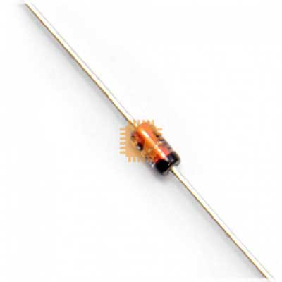
| Name | Original Zener Diode 9.1V 1/2W THT |
| Code | DI0314 |
| Price | Rs.10.00 |
| In Stock | Yes |
| Package | THT |
Product Details
The Original 9.1V 0.5W (1/2W) Through-Hole Zener Diode (DO-35 / 1N5239B / 1N757A) is a high-precision, silicon planar voltage-regulating diode designed for stable voltage reference generation, precision voltage clamping, and overvoltage circuit protection. Encapsulated in a hermetically sealed glass DO-35 axial package with tinned copper leads, it provides a stable 9.1V nominal breakdown voltage under reverse-bias conditions. Featuring a low dynamic Zener impedance and sharp reverse breakdown characteristics, this diode is widely used in linear power supplies, analog instrumentation, microcontroller ADC input protection circuits, bias-level shifting, and discrete voltage regulation stages.
Specifications
- Part Number / Standard Series: 1N5239B / 1N757A / BZX55C9V1 (9.1V 0.5W Series)
- Diode Type: Silicon Planar Zener Voltage Regulator Diode
- Package Type: DO-35 (Glass Axial Through-Hole Package)
- Nominal Zener Voltage ($V_Z$): 9.1 V (at $I_{ZT} = 20\text{ mA}$)
- Zener Voltage Tolerance: ±5% (B-Suffix Standard: 8.65 V to 9.56 V)
- Power Dissipation ($P_D$): 500 mW (0.5 W / 1/2 W at $T_L \le 75^\circ\text{C}$)
- Zener Test Current ($I_{ZT}$): 20 mA
- Maximum Dynamic Zener Impedance ($Z_{ZT}$): ≤ 30 Ω (at $I_{ZT} = 20\text{ mA}$)
- Maximum Knee Zener Impedance ($Z_{ZK}$): ≤ 600 Ω (at $I_{ZK} = 0.25\text{ mA}$)
- Maximum Reverse Leakage Current ($I_R$): ≤ 0.1 μA to 5.0 μA (at $V_R = 7.0\text{ V}$)
- Forward Voltage Drop ($V_F$): Typ. 0.9 V (Max. 1.1 V at $I_F = 200\text{ mA}$)
- Continuous Forward Current ($I_F$): 200 mA
- Maximum Continuous Zener Current ($I_{ZM}$): Approx. 50 mA to 55 mA (Thermally limited)
- Thermal Resistance (Junction to Ambient, $R_{\theta JA}$): 300 K/W to 400 K/W
- Operating Junction Temperature ($T_j$): -65°C to +200°C
- Storage Temperature Range ($T_{stg}$): -65°C to +200°C
- Lead Material / Finish: Solderable Tinned Copper Axial Leads
- Polarity Identification: Cathode indicated by a prominent black printed band on the glass body
Features
- Stable 9.1V Voltage Clamping: Delivers precise, low-noise voltage regulation across varying operating temperatures and load currents.
- Hermetically Sealed DO-35 Glass Body: Provides high reliability, excellent environmental and moisture protection, and long-term parameter stability.
- Sharp Reverse Breakdown Knee: Ensures quick transition into avalanche breakdown mode for crisp transient clipping and signal level shifting.
- Low Dynamic Impedance: Minimizes voltage drift across varying reverse current levels, maintaining a steady output rail.
- Standard Through-Hole Footprint: Easily mounts on universal breadboards, perfboards, and single/double-sided production PCBs.
Common Applications
- Analog Voltage References: Providing a stable 9.1V reference rail for operational amplifier circuits, comparators, and sensor bias networks.
- Microcontroller & ADC Input Protection: Clamping input voltages to protect sensitive ADC channels and logic pins against inductive spikes or overvoltage surges.
- Linear Shunt Regulators: Simple low-power DC voltage regulation from higher DC rails (e.g., deriving a stable 9.1V rail from 12V–24V supplies).
- MOSFET Gate-Source Protection: Clamping gate-to-source ($V_{GS}$) drive voltages to prevent gate oxide punch-through in high-side and low-side switching circuits.
- Relay & Solenoid Spike Suppression: Fast voltage-clipping networks paired with standard diodes for rapid inductive demagnetization.
Usage Tips
- Reverse-Bias Connection (Critical): Zener diodes operate in the **reverse-bias breakdown region**. Connect the **Cathode (banded end)** to the positive voltage side and the **Anode** to Ground / reference potential. Connecting it in forward bias will behave like a standard silicon diode ($V_F \approx 0.7\text{V}$).
- Current-Limiting Series Resistor ($R_S$): Never connect a Zener diode directly across a voltage source without a series current-limiting resistor. Calculate the series resistor using: $R_S = \frac{V_{IN(min)} - V_Z}{I_{LOAD(max)} + I_{ZK}}$, where $I_{ZK}$ is the minimum knee current (~2mA to 5mA) to keep the diode in stable regulation.
- Power Dissipation Management: Ensure the total power dissipated by the diode does not exceed its 500mW rating: $P_Z = V_Z \times I_Z \le 0.5\text{W}$. For maximum longevity and thermal stability, design the circuit so continuous dissipation is kept below **250mW to 300mW ($I_Z \le 30\text{mA}$)**.
- Soldering Precautions: Glass-encapsulated DO-35 diodes are sensitive to thermal and mechanical stress. Avoid sharp lead bends within 2 mm of the glass seal, and limit soldering dwell time to under 3–5 seconds at 260°C.
Sharing is caring, show love and share the product with your friends.
Featured


Add to Cart
Other Products

Add to Cart
