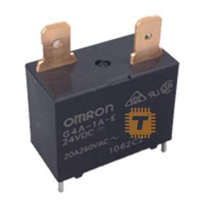
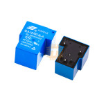
Songle Relay SLA-12VDC-SL-A 12VDC [30A 230VAC/30VDC] (RL0103) Products
![Songle Relay SLA-12VDC-SL-A 12VDC [30A 230VAC/30VDC]](https://tronic.lk/assets/uploads/42b7f7375c1049820678f5edc344111c.jpg)
| Name | Songle Relay SLA-12VDC-SL-A 12VDC [30A 230VAC/30VDC] |
| Code | RL0103 |
| Price | Rs.220.00 |
| In Stock | Yes |
| Package | THT |
Product Details
The Songle SLA-12VDC-SL-A is a high-power, heavy-duty T-shaped power relay engineered to handle exceptionally high electrical currents. Operating on a standard 12V DC coil circuit, it is capable of safely switching loads up to 30A at 230V AC or 30V DC. Unlike standard miniature PCB relays that max out at 10A, this robust component features beefy internal silver alloy contacts, making it an essential choice for managing high-wattage industrial machinery, large heating elements, and large electric motors.
Specifications
- Model Number: SLA-12VDC-SL-A
- Coil Nominal Voltage: 12V DC
- Coil Power Consumption: Approx 0.93W (High-sensitivity coil)
- Coil Resistance: Approx 155Ohm (10%)
- Contact Form / Configuration: SPST-NO (Single Pole Single Throw, Normally Open, Form A)
- Maximum Switching Current: 30A
- Maximum Switching Voltage: 250VA AC / 30V DC
- Maximum Contact Power Rating: 7200V (AC) / 900W (DC)
- Contact Material: AgSnO2 (Silver Tin Oxide for superior arc resistance)
- Dielectric Strength: 2,500V AC between coil and contacts (1 minute)
- Electrical Lifespan: ≥ 100,000 operations at rated load
- Mechanical Lifespan: ≥ 10,000,000 operations (unloaded)
- Terminal Layout: 4-Pin PCB Through-Hole (2 for coil, 2 for the high-power switch)
Features
- 30A True Power Switching: Built with dense structural contact surfaces that allow it to continuously switch high currents up to 30A, eliminating the need for a secondary magnetic contactor in mid-sized power rigs.
- Class F Insulation Profile: The internal wire windings are rated to withstand sustained temperatures up to 105℃, allowing the relay to function reliably inside hot control cabinets or near enclosed appliances.
- Sealed Flanged Housing: The "SL" prefix designates a sealed construction layout that keeps ambient dust, flux, and moisture from contaminating the switching contact points, extending its operational lifetime.
- Optimized T-Shape Footprint: The physical geometry isolates the low-voltage 12V coil pins on one side and groups the high-voltage 30A switching traces broadly on the opposite side, maximizing PCB creeping distances and preventing trace arc-overs.
Common Applications
- Smart Home Water Heaters: Controlling heavy storage water tanks and geysers that pull massive continuous electrical loads.
- Air Conditioners & HVAC: Triggering high-amperage cooling compressors and industrial air blower fans on and off.
- Electric Vehicle (EV) Chargers: Activating power delivery lines inside entry-level Level 1 and Level 2 AC charging stations.
- Industrial Automation: Powering heavy heating elements, kilns, conveyor motors, and solenoid valves from a central PLC.
Usage & Implementation Tips
- Do Not Drive Directly From a Microcontroller: The 12V coil draws roughly 60mA - 80mA when energized. Standard microcontroller output pins (like an Arduino, ESP32, or Raspberry Pi) can only output a maximum of 20mA - 40mA at 3.3V or 5V. You must use an intermediate NPN transistor (like a 2N2222) or a MOSFET (like a BS170) alongside a step-up 12V rail to drive the relay coil safely.
- Install a Flyback Protection Diode: Relay coils are highly inductive loads. When you turn the coil off, the collapsing magnetic field generates a massive high-voltage reverse spike (back-EMF) that can instantly destroy your driving transistor. Always solder a standard rectifier diode (like a 1N4007) in parallel across Pin 1 and Pin 2, with the cathode bar pointing toward your positive +12V input line.
- Design Heavy-Duty PCB Traces: Passing 30A through standard hobbyist PCB copper traces will instantly vaporize the board's copper traces. If you are designing a custom PCB for this relay, you must use wide traces, maximize your copper weight thickness (2 oz or higher), and strip away the solder mask over the power traces to layer them generously with physical solder wire or solid copper bus reinforcement bars.
- Factor in Inrush Currents: When driving inductive loads like electric motors or heavy power transformers, the starting current can spike up to 3 to 5 times higher than the running current. Ensure your device's initial startup spike does not stride past the 30A ceiling to prevent the contacts from arching and welding themselves together prematurely
Sharing is caring, show love and share the product with your friends.
Featured


Add to Cart