Vero Board Dot Epoxy FR4 12x8cm (TA1820) Products
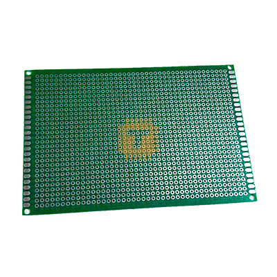
| Name | Vero Board Dot Epoxy FR4 12x8cm |
| Code | TA1820 |
| Price | Rs.170.00 |
| In Stock | Yes |
| Package | ACC |
Product Details
The 12x8cm High-Grade FR4 Epoxy Dot Matrix Vero Board (Single-Sided Prototype PCB) is a heavy-duty, professional prototyping perfboard engineered for building, hardwiring, and permanently securing electronic circuits. Manufactured from premium flame-retardant fiberglass-reinforced epoxy laminate (FR4) with a rigid 1.6 mm thickness, it offers superior mechanical stability, heat tolerance, and moisture resistance over standard single-sided Bakelite boards. Featuring a standard 2.54 mm (0.1-inch) grid populated with individually isolated, plated through-hole (PTH) tinned copper pads, it allows for smooth, reliable hand-soldering of DIP ICs, microcontrollers, terminal blocks, discrete components, and bus wiring for DIY electronics, robotics, and laboratory test benches.
Specifications
- Product Type: Universal Single-Sided Prototype Perfboard / Dot Matrix Vero Board
- Substrate Material: High-Grade FR4 (Flame-Retardant Glass-Fiber Reinforced Epoxy)
- Board Dimensions: 120 mm × 80 mm (12 × 8 cm / Approx. 4.72 × 3.15 inches)
- Board Thickness: Approx. 1.6 mm (Standard industrial PCB thickness)
- Pad Layout / Pattern: Matrix of Isolated Circular Solder Pads (Dot Matrix)
- Grid Pitch / Spacing: Standard 2.54 mm (0.1 inch) Center-to-Center Hole Pitch
- Hole Diameter: Approx. 1.0 mm (Accepts standard through-hole leads, DIP pins, and 2.54mm pin headers)
- Pad Plating / Finish: Pre-Tinned HASL (Hot Air Solder Leveling) for rapid wetting and oxidation resistance
- Hole Construction: Plated Through-Hole (PTH) with annular rings on both top and bottom copper layers
- Grid Matrix Count: Approx. 43 × 29 holes (Over 1,200 independent solder points)
- Mounting Holes: 4x Corner Mounting Holes (Approx. 3.0 mm to 3.2 mm diameter for M3 screws/standoffs)
- Dielectric Strength: ≥ 30 kV/mm
- Flammability Rating: UL 94V-0 Flame Retardant
- Operating Temperature Range: -40°C to +130°C
- Net Weight: Approx. 26 g
Features
- Large 12×8cm Prototyping Area: Provides ample layout space for complex, multi-stage circuit builds, power stages, and microcontroller sub-systems on a single unified board.
- Durable FR4 Epoxy Substrate: Resistant to warping, delamination, and excessive soldering heat, offering substantial structural strength compared to fragile paper-phenolic boards.
- Plated Through-Hole (PTH) Durability: Top and bottom copper pads are joined through the hole barrel, preventing pad lifting during rework or high-temperature soldering.
- Standard 2.54mm (0.1") Pitch Matrix: Fully compatible with DIP ICs, socket adapters, headers, relays, screw terminals, and standard passive components.
- Integrated M3 Corner Mounting: Four pre-drilled M3 mounting holes facilitate secure installation into project enclosures, chassis, or rack frames using standoffs.
- Flexible Point-to-Point Hardwiring: Isolated dot matrix format allows complete layout freedom for routing custom signal paths, ground planes, and power buses with jumper wires or solder bridging.
Common Applications
- Permanent DIY Circuit Assemblies: Converting completed solderless breadboard designs into permanent, rugged hardware modules.
- Microcontroller & Embedded Systems: Custom multi-module carrier boards for Arduino Nano/Mega, ESP32, STM32 Blue Pill, and Raspberry Pi Pico.
- Power Supply & Distribution Modules: Heavy-duty DC-DC regulation boards, multi-rail linear regulators, transformer rectification, and filter stages.
- Robotics & Motor Control: Assembling high-current MOSFET drivers, H-bridges, relay arrays, and multi-sensor routing hubs.
- Audio & Analog Electronics: Preamplifiers, active equalizer circuits, filter banks, and custom analog signal processing stages.
Usage Tips
- Creating Solder Bridges: To form clean conductive traces between adjacent pads, bend excess component leads along the track line to serve as a reinforcing core, then apply solder smoothly across the pads.
- Low-Impedance Power Buses: Given the large board dimensions, run dedicated solid 20–22 AWG tinned copper wire along the outer edges to establish heavy $V_{CC}$ and Ground (GND) distribution rails.
- Soldering Iron Temperature: Maintain soldering iron temperatures around **320°C to 350°C** for standard leaded solder or **350°C to 370°C** for lead-free solder. The FR4 laminate and PTH barrels ensure robust adhesion without heat damage.
- Enclosure & Standoff Mounting: Always use M3 nylon or brass hex standoffs in the four corner holes to elevate the board and prevent bottom-side solder joints from contacting conductive enclosures.
- Custom Sizing / Cutting: If a specific shape or smaller size is required, score both sides deeply along a steel ruler using a carbide PCB scoring tool or utility knife, snap along a workbench edge, and file smooth.
Sharing is caring, show love and share the product with your friends.
Featured


Add to Cart

Add to Cart
Other Products

Add to Cart