1.5pF Ceramic Capacitor THT (CA0025) Products
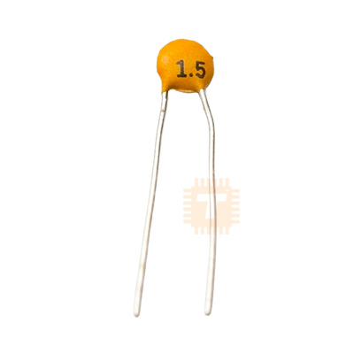
| Name | 1.5pF Ceramic Capacitor THT |
| Code | CA0025 |
| Price | Rs.1.00 |
| In Stock | Yes |
| Package | THT |
Product Details
The 1.5pF Ceramic Capacitor THT is a miniature, fixed-value Class 1 disc ceramic capacitor engineered for ultra-high-frequency (UHF/VHF) resonant circuits, RF impedance matching networks, oscillator load stabilization, and precision signal conditioning. Formulated with a temperature-compensating ceramic dielectric (typically NP0/C0G), it exhibits negligible capacitance drift across wide operating temperature envelopes, zero voltage coefficient of capacitance, and an exceptionally high Quality Factor (Q). Equipped with tinned through-hole (THT) radial copper leads, this component plugs easily into standard 2.54mm pitch solderless breadboards, stripboards, and PCB through-holes, providing low-loss capacitive coupling and minimal equivalent series resistance (ESR) for delicate RF and analog applications.
Specifications
- Capacitance Rating: 1.5 pF (Picofarads)
- Capacitance Tolerance: ±0.25 pF or ±0.5 pF (Tight tolerance standard for sub-10pF values)
- Dielectric Material: Class 1 Temperature-Compensating Ceramic (NP0 / C0G)
- Rated Voltage (VDC): 50 V DC (Standard industrial dielectric breakdown rating; withstands transient spikes up to 100 V DC)
- Mounting Type: Radial Through-Hole Technology (THT)
- Lead Pitch / Spacing: 2.54 mm (0.1 Inch) or 5.08 mm (0.2 Inch)
- Lead Material: Tinned Copper Wire (Sn-plated for fast solder wetting)
- Lead Wire Gauge: Approx. 24 AWG to 26 AWG (0.4 mm to 0.5 mm diameter)
- Temperature Coefficient: 0 ± 30 ppm/°C (Ultra-stable C0G/NP0 characteristic)
- Insulation Resistance (IR): ≥ 10,000 MΩ (Measured at rated DC voltage)
- Dissipation Factor (tan δ): ≤ 0.1% (High Q factor ≥ 400 + 20C at 1 MHz)
- Operating Temperature Range: -55°C to +125°C
- Body Coating: Flame-Retardant Epoxy Resin Coating (UL 94V-0 compliant)
- Disc Diameter: Approx. 3.0 mm to 5.0 mm
- Net Weight: Approx. 0.1 g to 0.2 g per unit
Features
- Ultra-Stable Class 1 Dielectric: Built with NP0/C0G ceramic composition to guarantee that capacitance remains flat without drift across changing temperatures, applied voltages, or frequencies.
- Non-Polarized Construction: Symmetrical bipolar configuration allows error-free bidirectional installation in both AC signal paths and DC bias circuits.
- Negligible Dielectric Absorption & Low ESR: Delivers minimal internal energy loss and ultra-low phase noise, making it suitable for crystal oscillators, RF synthesizers, and antenna front-ends.
- Standard Breadboard Compatibility: Radial leads with standard 2.54mm or 5.08mm spacing plug directly into solderless breadboards and prototyping perfboards without lead trimming or bending.
- Rugged Moisture-Resistant Shell: Sealed in an epoxy dip coating that protects the internal silver-electrode ceramic disc against ambient moisture, flux corrosion, and mechanical vibration.
Common Applications
- RF & Wireless Transceivers: Tuning and impedance-matching networks for 433 MHz, 868 MHz, 915 MHz, and 2.4 GHz wireless transceivers.
- Crystal Oscillator Loading: Fine-tuning load capacitance ($C_L$) for high-frequency quartz crystals and ceramic resonators on microcontrollers (ESP32, STM32, AVR).
- Active Bandpass & Notch Filters: Precise frequency determination in high-order active analog filters and low-noise RF preamplifiers.
- High-Speed Digital Edge Snubbing: Filtering parasitic ringing, cross-talk spikes, and high-frequency noise glitches on sensitive logic signal lines.
- Audio & Instrument Preamps: Feedback loop compensation in ultra-high-speed operational amplifiers to prevent self-oscillation.
Usage Tips
- Stray Capacitance Consideration (CRITICAL):
- Because 1.5 pF is an exceptionally small capacitance value, **parasitic capacitance from long PCB traces, adjacent wiring, or breadboard tie-point strips (often 1 pF to 3 pF)** can easily equal or exceed the value of the capacitor itself.
- For high-frequency or RF circuits, trim the radial leads as short as possible and solder the capacitor directly next to the target IC pin or crystal terminal.
- Avoid using standard solderless breadboards for RF testing at frequencies above 30 MHz, as internal metal clip capacitance will distort circuit resonance.
- Soldering Temperature & Dwell Time:
- Maintain soldering iron tip temperature between 300°C and 350°C.
- Limit soldering dwell time to under 3 seconds per lead, keeping the iron tip at least 2 mm away from the epoxy body to prevent thermal shock fractures inside the ceramic disc.
- Proper Lead Bending: When bending leads for custom hole spacing, support the lead wire with needle-nose pliers near the epoxy base before applying bend force. Bending leads directly against the resin coating can crack the seal and expose internal silver electrodes to ambient moisture.
- Polarity & Orientation: As a ceramic capacitor, it is non-polarized; either lead can be connected to the positive signal rail or ground reference without affecting electrical characteristics.
- Voltage Safety Margins: While rated for 50V DC, maintain a 20% to 50% voltage safety derating for circuits exposed to harsh inductive switching or power line spikes to ensure long-term dielectric reliability.
Sharing is caring, show love and share the product with your friends.
Featured

Add to Cart


Add to Cart
Other Products

Add to Cart

Add to Cart