1-Channel Relay Module for ESP8266 ESP-01S (MD0235) Products
Name
1-Channel Relay Module for ESP8266 ESP-01S
Code
MD0235
Price
Rs.380.00
In Stock
Yes
Package
MODULE
Product Details
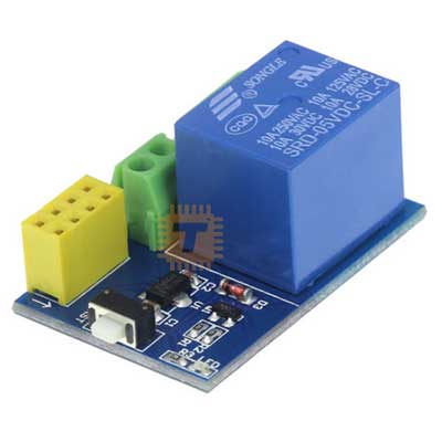
This relay module is specifically designed for the ESP-01 or ESP-01S WiFi transceiver. It serves as a smart switch, allowing the low-voltage ESP8266 to control high-voltage AC or DC appliances via WiFi. The module features a socket that directly fits the ESP-01S, making it a plug-and-play solution for IoT projects like smart home automation.
Specifications
Operating Voltage: DC 5V.
Relay Control Pin: GPIO0 (on the ESP-01/01S).
Relay Type: SRD-05VDC-SL-C.
Switching Capacity:
AC: 250V / 10A.
DC: 30V / 10A.
Transmission Distance: Depends on the WiFi signal strength of the ESP-01S.
Features
ESP-01S Compatibility: Features a dedicated 2x4 female header to secure the ESP-01S module directly.
Low-Level Trigger: Designed to activate the relay when the ESP-01S GPIO0 is pulled low.
Status Indicator: Includes an onboard LED that lights up when the relay is energized.
Simplified Wiring: Uses a 3-pin screw terminal for the load (NO, COM, NC), eliminating the need for soldering the high-voltage connections.
Optocoupler Isolation: Provides electrical isolation between the ESP-01S and the high-power load to prevent interference and damage.
Pin and Terminal Guide
VCC / GND: 5V Power Input for the module and the relay coil.
ESP-01S Header: 8-pin socket for the WiFi module.
Relay Output:
NO (Normally Open): The circuit is open until the relay is triggered.
COM (Common): The shared terminal for the load power.
NC (Normally Closed): The circuit is closed by default and opens when triggered.
Common Applications
Smart Lighting: Controlling household bulbs via a mobile app or web server.
Remote Power Reset: Hard-resetting servers or routers over WiFi.
Home Automation: Integrating non-smart appliances into systems like Home Assistant or Blynk.
DIY Smart Plugs: Building custom, compact WiFi-controlled sockets.
Usage Tips
Power Supply: Ensure your 5V power supply can provide at least 250mA to handle the current surge when the relay coil energizes.
Programming: When writing code (e.g., Arduino IDE), set GPIO0 as an OUTPUT. Send a LOW signal to turn the relay "On" and a HIGH signal to turn it "Off".
Safe Mounting: Since the bottom of the PCB contains high-voltage traces, always mount the module in a non-conductive plastic enclosure to prevent electrical shock.
GPIO0 Conflict: Note that GPIO0 must be HIGH during the ESP8266 boot process to enter "Run Mode." If the relay is wired such that it pulls GPIO0 down during startup, the module may fail to boot correctly.
Essential Hardware Fixes
Remove Resistor R2 (Labelled '202'): This 2kΩ pulldown resistor on GPIO0 prevents the ESP8266 from booting into the correct mode. Removing it allows the module to start up normally.
Bridge CH_PD (EN) to VCC: The Chip Enable pin is often left floating on these boards. You must create a wire bridge or solder a connection between the CH_PD pin and 3.3V (VCC) to enable the chip.
Please refer to the following pages.
The following page refers to the first modification only. So first do it and see it fixes the issue.