Adjustable Delay Timer Switch 5-30V MicroUSB Power (MD0520) Products

| Name | Adjustable Delay Timer Switch 5-30V MicroUSB Power |
| Code | MD0520 |
| Price | Rs.480.00 |
| In Stock | Yes |
| Package | MODULE |
Product Details
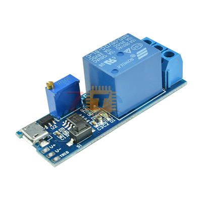
The Adjustable Delay Timer Module is a versatile trigger-delay switch that uses a 555-based timing circuit to control a high-power relay. It features dual power input options (screw terminals or MicroUSB) and is designed for high stability in industrial environments. Once triggered by a button press or an external pulse, the relay activates for a set duration (0-24 seconds) before automatically switching off.
Specifications
- Operating Voltage: Wide voltage DC 5V to 30V
- Power Interfaces: 2-pin Screw Terminal or MicroUSB (5V)
- Trigger Signal: High Level (3.0V to 24V) or built-in trigger button
- Output Capacity:
- AC: 250V / 10A
- DC: 30V / 10A
- Delay Time: Default 0 to 24 seconds (Adjustable)
- Timing Formula: T = 1.1 * R * C
Operating Mode
- Initial State: The relay is "Off." The Common (COM) terminal is connected to the Normally Closed (NC) terminal, and the Normally Open (NO) terminal is disconnected.
- Triggered State: When a high pulse signal is provided or the trigger button is pressed, the relay activates and the indicator light turns on. The COM terminal connects to the NO terminal.
- Delay Sequence: The relay stays "On" for the duration set by the potentiometer.
- Reset: After the time elapses (0-24s), the relay automatically switches off and returns to the initial state, waiting for the next trigger.
Features
- Dual Power Input: Can be powered easily via a standard 5V MicroUSB phone charger or a DC power supply (up to 30V).
- High Anti-Interference: The trigger input is designed with a pull-up and filter circuit, making it stable in electromagnetic environments or during power-up/down moments.
- Adjustable Timing: The delay length is adjusted via an onboard multi-turn potentiometer. For longer delays, the C2 capacitor or the potentiometer can be replaced with higher values.
- Passive Relay Contacts: The relay acts as a simple switch (dry contacts) and does not output electricity itself, allowing it to control different voltage circuits than the one powering the module.
- Freewheeling Protection: Includes an onboard diode to protect the circuit from inductive voltage spikes when the relay coil de-energizes.
Pin and Terminal Guide
- Input Side:
- V+ / V-: DC Power Input (5V to 30V).
- MicroUSB: 5V Power Input.
- Trig: External trigger signal input.
- Output Side (Relay):
- NO (Normally Open): Connected to COM only when triggered.
- COM (Common): The shared terminal for the load.
- NC (Normally Closed): Connected to COM by default when the timer is idle.
Common Applications
- Anti-Theft Alarms: Delaying the activation of a siren or light after a sensor is tripped.
- Equipment Protection: Delaying the start of heavy machinery to prevent power surges.
- Automotive Electronics: Keeping cabin lights or accessories on for a short period after the ignition is turned off.
- Smart Home: Controlling the "On" time for exhaust fans, pumps, or magnetic door locks.
Usage Tips
- Time Extension: To increase the delay beyond 24 seconds, you can solder a larger capacitor in place of C2. For example, a 220uF capacitor would increase the max delay to approximately 242 seconds.
- Trigger Isolation: The signal ground and system ground are separate to increase anti-interference, but they can be short-circuited together if a common ground is required for your specific trigger source.
- Passive Switching: Remember that the relay terminals act as a switch, not a power source. You must wire your load's power supply in series with the COM and NO terminals.
Sharing is caring, show love and share the product with your friends.
Featured


Add to Cart

Other Products
Add to Cart

Add to Cart

Add to Cart
