FNIRSI DPOF1204 200MHz Quad Channel 1GSa/s Digital Phosphor Oscilloscope (TA1966) Products
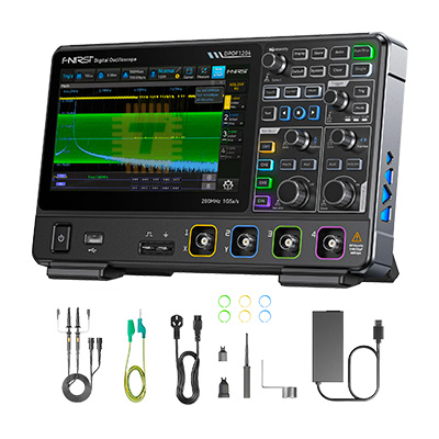
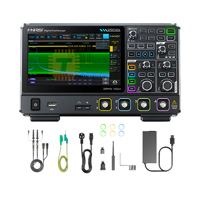
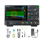
| Name | FNIRSI DPOF1204 200MHz Quad Channel 1GSa/s Digital Phosphor Oscilloscope |
| Code | TA1966 |
| Price | Rs.1,90,850.00 |
| In Stock | Yes |
| Package | MODULE |
Product Details
The FNIRSI DPOF1204 200MHz Quad Channel 1GSa/s Digital Phosphor Oscilloscope is an advanced, high-performance benchtop digital phosphor oscilloscope (DPO) engineered for embedded hardware design, power electronics debugging, RF analysis, and automated multi-channel signal inspection. Featuring four independent analog channels, an analog bandwidth of 200 MHz, and a real-time sampling rate of up to 1 GSa/s, it employs digital fluorescence technology with 256-level color grading and intensity modulation. This architecture enables the visual capture of low-probability signal anomalies, transient glitches, jitter, and complex modulated waveforms with high waveform capture rates, making it an indispensable tool for mixed-signal debugging, SPI/I2C/UART serial bus analysis, and high-frequency power stage evaluation.
Specifications
- Instrument Model: FNIRSI DPOF1204 (DPO Series)
- Oscilloscope Architecture: 4-Channel Digital Phosphor Oscilloscope (DPO)
- Analog Channels: 4 Independent Analog Input Channels (CH1, CH2, CH3, CH4)
- Analog Bandwidth: 200 MHz (-3 dB cutoff frequency across all channels)
- Real-Time Sampling Rate: Up to 1 GSa/s (1 GS/s single-channel/interleaved, 500 MSa/s dual-channel, 250 MSa/s 4-channel active)
- Memory Depth / Record Length: Up to 14 Mpts to 28 Mpts (Deep hardware acquisition buffer)
- Waveform Capture Rate (WFM/s): Up to 50,000 wfm/s in standard mode (up to 100,000+ wfm/s in fast sequence mode)
- Vertical Resolution: 8-Bit Hardware ADC (Hardware high-resolution averaging mode up to 12-Bit)
- Vertical Sensitivity Scale: 1 mV/div to 10 V/div (Standard 1-2-5 step sequence at 1 MΩ input)
- Timebase Range: 2 ns/div to 100 s/div
- Input Impedance & Coupling: 1 MΩ ±2% || ~15 pF; AC, DC, and GND coupling modes
- Maximum Direct Input Voltage:
- At 1X Probe Setting: 40 V (DC + AC Peak)
- At 10X Probe Setting: 400 V (DC + AC Peak)
- Category: CAT II 300V standard compliance
- Display Technology:
- Panel Type: 7.0-Inch TFT LCD High-Resolution Color Screen (800 × 480 or 1024 × 600 resolution)
- Phosphor Grayscale: 256-Level Color Temperature / Intensity-Graded Fluorescence Display
- Trigger Capabilities:
- Trigger Modes: Auto, Normal, Single-Shot
- Trigger Types: Edge, Pulse Width, Video (NTSC/PAL/SECAM), Slope, Overtime/Timeout, Runt, Pattern, and Window
- Serial Bus Trigger & Decode: Hardware decoding for I2C, SPI, UART/RS232, CAN, and LIN protocols
- Math & Analysis Functions:
- Arithmetic: A+B, A-B, A×B, A/B, Invert
- Spectral Analysis: Hardware Fast Fourier Transform (FFT) with Hanning, Hamming, Blackman, and Rectangular windows
- Automatic Parameter Measurements: 30+ automated measurements (Vpp, Vmax, Vmin, Vavg, Vrms, Frequency, Period, Rise/Fall Time, Duty Cycle, Phase, Delay)
- Built-in Auxiliary Generator: Optional Integrated 25–50 MHz Dual-Channel Arbitrary Function Generator (DDS AFG module)
- Connectivity & Expansion: USB Host (USB flash drives, mouse), USB Device (PC interface / SCPI protocol compliance), Pass/Fail BNC trigger output, and Aux Out
- Operating Power Supply: Universal AC 100 V to 240 V, 50/60 Hz (Standard IEC power cord input)
- Physical Dimensions: Approx. 340 × 175 × 90 mm
- Instrument Net Weight: Approx. 2.2 kg to 2.6 kg
Features
- 256-Level Digital Phosphor Display: Real-time intensity and color-temperature grading reveals the statistical frequency of signal occurrences, making elusive runt pulses, clock jitter, and parasitic ringing stand out instantly in vibrant visual detail.
- Full Quad-Channel Concurrent Acquisition: Four fully isolated analog channels allow concurrent monitoring of 3-phase motor inverter drive gates, multi-rail SMPS power sequencing, or complete 4-wire SPI communication buses (CS, CLK, MOSI, MISO).
- Deep Hardware Memory Depth: Multi-megapoint acquisition memory maintains high 1GSa/s sampling fidelity even across long horizontal sweep windows, allowing users to zoom in on transient high-frequency noise bursts embedded inside low-frequency cycles.
- Integrated Hardware Serial Protocol Decoding: Native hardware-accelerated decoding of I2C, SPI, UART, and CAN buses displays decoded hex/ASCII data directly below analog waveforms, eliminating tedious manual bit-counting on microcontrollers.
- High-Speed Hardware FFT Spectrum Analysis: Provides real-time frequency-domain visibility to track electromagnetic interference (EMI), switch-mode harmonic content, and audio distortion profiles.
- Comprehensive Auto-Measurement & Cursor Gating: Real-time statistical tracking of up to 30 parameters simultaneously, complete with standard deviation, minimum, maximum, and mean readouts.
Common Applications
- Embedded Systems & Firmware Debugging: Troubleshooting timing skews, bus contention, and protocol packet errors on STM32, ESP32, Arduino, and FPGA systems.
- Power Electronics & Inverter Development: Measuring high-side and low-side gate driver waveforms, drain-to-source (Vds) voltage spikes, and inductive reverse recovery on GaN/SiC/MOSFET switching stages.
- Automotive Electronics & CAN Bus Diagnostics: Decoding automotive sensor packets, analyzing ECU communications, and tracing intermittent harness faults.
- Audio & Analog Circuit Design: Evaluating operational amplifier bandwidth, signal distortion, clipping thresholds, and phase margins across active filters and audio preamps.
- RF & Wireless Transmitter Testing: Verifying modulation envelopes, clock synthesizer stability, and high-frequency carrier wave characteristics up to 200 MHz.
Usage Tips
- Probe Attenuation & Compensation (CRITICAL):
- Always verify that the 1X/10X slide switch on your BNC probe matches the vertical channel attenuation setting in the oscilloscope firmware. Misaligned probe settings result in a 10× voltage measurement error.
- Perform frequency compensation before taking measurements: connect the probe to the front-panel 1 kHz calibration terminal and adjust the trimmer capacitor screw on the probe barrel until the displayed square wave exhibits perfectly square, flat corners (neither rounded nor overshooting).
- Measuring High-Voltage & Floating Power Circuits:
- The outer ground shield of every BNC input is internally connected to Earth Ground through the instrument's mains power cord.
- Never connect standard probe alligator ground clips to "hot" floating potentials (such as the high-side MOSFET source in a half-bridge or rectified mains lines). Doing so creates an immediate dead short to ground that will vaporize the probe ground lead and damage the scope.
- For floating measurements, always use a dedicated high-voltage active differential probe or use the math channel to calculate the difference between two channels (CH1 - CH2) with both probe grounds securely clamped to earth.
- Leveraging Digital Phosphor for Intermittent Glitches:
- When hunting for elusive runt pulses, missing clock edges, or sporadic bus resets, set the display persistence from "Normal" to "Infinite" or "Color Grade" and adjust the trigger mode to "Normal" or "Single".
- Rare intermittent anomalies will appear as faint traces or distinct cooler color bands (e.g., blue/violet) against the dense primary signal waveform (red/orange).
- High-Frequency Grounding Techniques (200 MHz):
- Standard 15 cm alligator ground clips act as substantial inductors at frequencies above 50 MHz, introducing artificial ringing and overshoot into measured square wave edges.
- When measuring high-speed clock lines or fast MOSFET gate rise times, remove the long alligator clip and slip-on hook tip, and install the short, coiled ground spring directly onto the probe tip barrel.
- Memory Depth vs. Responsiveness:
- While deep memory captures long record durations, setting maximum memory depth can slow down the screen refresh rate on complex 4-channel setups.
- For interactive bench tuning and real-time knob adjustments, set memory depth to automatic or moderate values (1 Mpts); switch to maximum deep memory (14M/28M) when capturing single-shot serial data trains for post-trigger zoom analysis.
Sharing is caring, show love and share the product with your friends.
Featured

Add to Cart


Add to Cart

Other Products

Add to Cart

Add to Cart