MCP23017 Bidirectional 16-Bit IO Extension Expander Module IIC I2C SPI 10MHz (MD0477) Products

We are sorry but the product is out of stock, please check back after few days.
| Name | MCP23017 Bidirectional 16-Bit IO Extension Expander Module IIC I2C SPI 10MHz |
| Code | MD0477 |
| Price | Rs.3,300.00 |
| In Stock | No |
| Package | MODULE |
Product Details
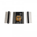
The MCP23017 is a powerful 16-bit, general-purpose parallel I/O expansion module for the I2C bus. It allows you to add 16 digital pins to your microcontroller using only two wires (SDA and SCL). This module is highly configurable, featuring dual interrupt outputs and hardware addressing, making it a standard choice for complex projects requiring extensive user interfaces or sensor arrays.
Specifications
- I/O Count: 16-bit remote bidirectional I/O port.
- Operating Voltage: 1.8V to 5.5V.
- Interface: High-speed I2C (100kHz, 400kHz, and 1.7MHz support).
- Standby Current: Ultra-low 1 uA (max).
- Clock Speed: SPI variant (MCP23S17) supports up to 10MHz, while this I2C variant handles up to 1.7MHz.
- Operating Temperature: Industrial grade (-40°C to +125°C).
Features
- 16 Independent I/O Pins: All pins default to "Input" on power-up to prevent accidental damage to connected components.
- Configurable Interrupts: Features two interrupt pins (INTA and INTB) that can be configured to operate independently for each 8-bit port or "mirrored" to work together. They can be set as active-high, active-low, or open-drain.
- Hardware Addressing: Three hardware address pins allow up to eight modules to coexist on the same I2C bus, providing a total of 128 additional I/O pins.
- Polarity Inversion: Includes a register to flip the polarity of input data, simplifying code logic for active-low sensors.
- External Reset: Dedicated reset input allows for hardware-level initialization of the module.
Pin Configuration
- VDD / VSS: Power (1.8V–5.5V) and Ground.
- SCL / SDA: I2C Serial Clock and Data lines.
- GPA0–GPA7: 8-bit Port A I/O pins.
- GPB0–GPB7: 8-bit Port B I/O pins.
- INTA / INTB: Interrupt outputs for Port A and Port B.
- ADDR (A0, A1, A2): Hardware address pins.
- RESET: External reset pin (Active Low).
Common Applications
- Keypad Matrices: Scanning large 4x4 or 8x8 button grids efficiently.
- LED Drivers: Driving up to 16 individual LEDs or segments with high-current capability.
- System Expansion: Adding many digital inputs (switches/limit sensors) to pin-limited boards like the ESP8266.
- User Interface Panels: Managing multiple buttons and status lights on a control console.
Usage Tips
- Interrupt-on-Change: Configure the module to trigger an interrupt only when a pin state changes. This allows your microcontroller to perform other tasks or stay in sleep mode until an input event occurs.
- I2C Pull-ups: Ensure your I2C bus has 4.7k or 10k pull-up resistors. Many breakout boards include these, but verify if you are using multiple modules.
- Addressing: Connect A0, A1, and A2 to either GND or VDD to set the I2C address. If left floating, the address may become unstable.
- Logic Level: Ensure the VDD matches the logic level of your microcontroller (e.g., 3.3V for ESP32/Pi, 5V for Arduino Uno) to avoid communication issues.
Sharing is caring, show love and share the product with your friends.
Featured


Add to Cart
Other Products


Add to Cart

Add to Cart

