Original 74LS47 Decoder BCD to 7-Segment (74HC47) PDIP-16 (IC0367) Products
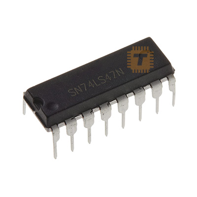
| Name | Original 74LS47 Decoder BCD to 7-Segment (74HC47) PDIP-16 |
| Code | IC0367 |
| Price | Rs.380.00 |
| In Stock | Yes |
| Package | PDIP-16 |
Product Details
The Original 74LS47 BCD to 7-Segment Decoder / Driver IC (Active-Low Open-Collector / PDIP-16) is a standardized Low-Power Schottky TTL integrated circuit engineered to accept a 4-bit Binary Coded Decimal (BCD: A, B, C, D) input and decode it into the corresponding active-low outputs (a through g) to directly drive Common Anode 7-segment LED displays. Featuring high-voltage, open-collector output transistors capable of sinking up to 24 mA per segment and withstanding off-state collector voltages up to 15 V, it eliminates the need for external buffer transistors. It includes dedicated control pins for lamp test (LT), ripple-blanking input/output (RBI / RBO), and blanking input (BI) for leading/trailing zero suppression and display intensity modulation via PWM. Encapsulated in a standard 16-pin plastic dual in-line package (PDIP-16), it is a staple in digital electronics, instrumentation panels, frequency counters, and microcontroller I/O expander circuits.
Specifications
- Part Number / Logic Family: SN74LS47N / 74LS47 (Low-Power Schottky TTL Series)
- Function: BCD to 7-Segment Decoder / Driver with Open-Collector Outputs
- Package Type: PDIP-16 (Plastic Dual In-Line Package, 16-Lead, Standard 0.1" / 2.54 mm Pitch)
- Display Drive Compatibility: Common Anode (Active-Low Outputs: a, b, c, d, e, f, g)
- Supply Operating Voltage (VCC): 4.75 V to 5.25 V DC (Nominal 5.0 V DC)
- Input Voltage High Level (VIH): Min. 2.0 V
- Input Voltage Low Level (VIL): Max. 0.8 V
- Maximum Output Breakdown Voltage (VOH / Collector Off-State): Up to 15.0 V Max. (Active-Low Open Collector)
- Maximum Output Sink Current (IOL):
- Segment Outputs (a through g): Up to 24.0 mA per segment (Continuous sink)
- Ripple-Blanking Output (RBO): Up to 3.2 mA
- Typical Propagation Delay Time: Approx. 35 ns to 45 ns (from BCD input to segment output)
- Total Power Dissipation (PD): Approx. 35 mW to 40 mW Typ.
- Operating Ambient Free-Air Temperature (TA): 0°C to +70°C
- Storage Temperature Range: -65°C to +150°C
Features
- Direct Open-Collector Drive: Internal high-voltage open-collector NPN stages sink up to 24 mA directly, allowing segments to be powered from 5V or higher auxiliary rails (up to 15V) without auxiliary driver transistors.
- Active-Low Segment Outputs: Configured specifically to drive Common Anode 7-segment LED displays.
- Comprehensive Control Inputs:
- Lamp Test (overline LT): Instantly overrides all BCD inputs and turns all 7 segments ON for display diagnostic checking.
- Blanking Input (overline BI): Overrides all inputs to turn all segments OFF, facilitating PWM brightness dimming.
- Ripple-Blanking (overline RBI / overline RBO: Automatically extinguishes leading or trailing zeroes across multi-digit display cascades.
- Standardized BCD Decoding: Reliably decodes decimal numerals 0 through 9, and outputs unique fault patterns for non-BCD hexadecimal values (10 through 15 / A–F).
- Breadboard & Socket Friendly: Standard 0.1" (2.54 mm) pin pitch allows direct insertion into prototyping breadboards and standard 16-pin IC sockets.
Common Applications
- Digital Panel Meters & Clocks: Decoding counter outputs (such as 74LS90 / 74HC390 BCD ripple counters) into numerical displays.
- Microcontroller I/O Saving: Reducing GPIO requirements by driving multiple 7-segment displays using only 4 data lines from an Arduino, PIC, or ESP32.
- Industrial Control Displays: Indicating machine speed, batch counts, temperature channels, and process setpoints.
- Educational Digital Logic Labs: Practical demonstration of BCD encoding, combinatorial logic decoding, and truth table verification.
Usage Tips
- Display Selection (Common Anode Required): The 74LS47 features active-low open-collector sink outputs and must be paired with a Common Anode 7-segment display (Common pin tied to +5V). It will not drive Common Cathode displays (use a 74LS48 for active-high Common Cathode driving).
- Current-Limiting Resistors (Mandatory): Never connect the segment outputs directly to the display pins. Place a series current-limiting resistor (220Ω to 470Ω, 1/4W) on each individual segment line (a through g) to set LED current between 5 mA and 15 mA.
- Unused Control Pins Connection (CRITICAL):
- For normal display operation without zero-blanking, tie Pin 3 (overline LT), Pin 4 (overline BI / overline RBO), and Pin 5 (overline RBI) high to +5V (VCC).
- Leaving overline LT floating low or grounded will force all segments permanently ON regardless of BCD data.
- Decoupling Capacitor: Place a standard 0.1 μF (100 nF) ceramic capacitor directly across Pin 16 (VCC) and Pin 8 (GND) close to the IC body to filter logic switching noise.
- PWM Brightness Dimming: Modulate the display brightness by applying a high-frequency (1 kHz–5 kHz) PWM signal to Pin 4 (overline BI); varying the duty cycle adjusts perceived display luminance smoothly.
Sharing is caring, show love and share the product with your friends.
Featured

Add to Cart


Add to Cart