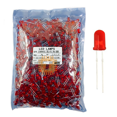
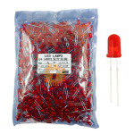
Original LED 5mm Red Diffused Pack Production Quality (1000Pcs) (LE0144) Products
We are sorry but the product is out of stock, please check back after few days.
| Name | Original LED 5mm Red Diffused Pack Production Quality (1000Pcs) |
| Code | LE0144 |
| Price | Rs.2,750.00 |
| In Stock | No |
| Package | THT |
Product Details
The Original 5mm Red Diffused LED (Production Quality - Pack of 1000 Pcs) is a commercial-grade through-hole light-emitting diode engineered for high-volume PCB manufacturing, electronic instrumentation, and front-panel status indication. Encapsulated in a standard T-1 3/4 (5mm) red diffused epoxy resin lens, it integrates a high-efficiency GaAsP/GaP (Gallium Arsenide Phosphide on Gallium Phosphide) semiconductor chip that emits a rich, uniform 620nm–630nm red light with a wide 60° viewing angle. Built with pure copper leadframes for optimal thermal dissipation and high-integrity gold-wire bonding, these LEDs provide exceptional optical and electrical consistency across all 1000 pieces in the production pack. They are widely utilized in industrial automation panels, audio equipment peak indicators, fault alarms, consumer electronics, and educational robotics kits.
Specifications
- Product Type: 5mm (T-1 3/4) Red Diffused Through-Hole LED (Pack of 1000 Pieces)
- Lens Type / Appearance: 5mm Round Red Tinted Diffused Epoxy Lens
- Emitted Light Color: Red
- Dominant Wavelength (λd): 620 nm to 630 nm (Peak Wavelength λp ≈ 635 nm to 640 nm)
- Semiconductor Material: GaAsP/GaP (Gallium Arsenide Phosphide on Gallium Phosphide) / AlGaInP
- Luminous Intensity (Iv): 60 mcd to 150 mcd (at IF = 20mA, uniform diffused distribution)
- Viewing Angle (2θ1/2): 60° (Wide-angle diffused beam pattern)
- Forward Voltage Drop (VF): Typ. 1.9V to 2.0V / Max. 2.4V (at IF = 20mA)
- Continuous Forward Current (IF): 20mA (Nominal) / Max. 30mA (Absolute Maximum)
- Peak Pulse Forward Current (IFP): Up to 100mA (1/10 Duty Cycle, 0.1ms Pulse Width)
- Reverse Breakdown Voltage (VR): Min. 5.0V (at IR = 10µA)
- Reverse Leakage Current (IR): Max. 10µA (at VR = 5V)
- Power Dissipation (Pd): 75mW to 100mW (at Ta = 25°C)
- Electrostatic Discharge (ESD) Threshold: Up to 2000V (HBM)
- Lead Pitch / Spacing: Standard 2.54mm (0.1-inch)
- Lead Material & Plating: Pure Copper Alloy with Tin/Silver Electroplating for High Solderability
- Polarity Identification: Longer Lead: Anode (+), Shorter Lead & Flat Lens Rim: Cathode (-)
- Operating Temperature Range (Topr): -40°C to +85°C
- Storage Temperature Range (Tstg): -40°C to +100°C
- Lead Soldering Temperature: 260°C for max. 3 to 5 seconds (at 2mm distance from epoxy base)
Features
- Red Diffused Lens Design: Softens and spreads light evenly across a wide 60° viewing angle, eliminating sharp hot spots and ensuring clear off-axis visibility on status panels.
- Production-Grade Batch Consistency: Strict binning ensures tightly matched forward voltage (VF ~2.0V) and uniform luminous output across all 1000 units.
- High-Conductivity Copper Leads: Thick copper alloy leadframes dissipate thermal energy away from the semiconductor junction, ensuring long operating life and high mechanical strength.
- Low Forward Voltage Drop: Operates at a low typical forward drop of 1.9V–2.0V, making it easy to drive directly from 3.3V and 5V microcontroller GPIOs with minimal power dissipation.
- Universal 2.54mm Lead Pitch: Standard T-1 3/4 footprint fits seamlessly into prototype breadboards, stripboards, automated PCB insertion machines, and panel-mount LED bezels.
Common Applications
- Industrial Control & Safety Panels: Power-off, stop, fault condition, and emergency alarm pilot indicators.
- Audio & Studio Equipment: VU meter peak level clips, channel mute lights, and power rail status indicators.
- Consumer Appliances & Power Supplies: Standby/charging status indicators on battery chargers, power strips, and UPS systems.
- Microcontroller & Robotics Projects: Standard benchtop debug LEDs for Arduino, ESP32, Raspberry Pi, STM32, and CH32V boards.
- Logic Analyzers & Test Jigs: Visual logic-level indicators and circuit continuity check points.
Usage Tips
- Always Use a Current-Limiting Resistor: **Never connect the LED directly across a voltage source without a series current-limiting resistor**, as the unconstrained current will burn out the LED die instantly.
- Series Resistor Calculation Formula: R_series = (Vsupply - VF) / IF.
- From a +3.3V GPIO Rail (at IF = 10mA, VF = 2.0V): R = (3.3V - 2.0V) / 0.01A = 130Ω (Standard 130Ω or 150Ω, 1/8W resistor recommended).
- From a +5.0V Logic Rail (at IF = 15mA, VF = 2.0V): R = (5.0V - 2.0V) / 0.015A = 200Ω (Standard 220Ω, 1/4W resistor recommended).
- From a +12.0V Supply (at IF = 15mA, VF = 2.0V): R = (12.0V - 2.0V) / 0.015A = 667Ω (Standard 680Ω or 750Ω, 1/4W resistor recommended).
- From a +24.0V Industrial Rail (at IF = 15mA, VF = 2.0V): R = (24.0V - 2.0V) / 0.015A = 1467Ω (Standard 1.5kΩ, 1/2W power resistor recommended).
- Polarity Identification: Connect the longer lead to the positive rail (Anode +) and the shorter lead to the low-side switch or ground (Cathode -). When leads are cut, identify the Cathode by the flat notched edge along the bottom rim of the epoxy lens.
- Direct Microcontroller Driving: With a low ~2.0V forward drop, this LED is well-suited for direct connection to 3.3V logic pins (e.g., ESP32, STM32) using a 150Ω to 220Ω series resistor to safely draw under 10mA per pin.
- Soldering Guidelines: Maintain at least a 2mm gap between the soldering iron tip and the bottom of the epoxy body. Limit iron contact time to under 3–5 seconds at 260°C to protect the internal bonding wire from thermal fatigue.
Sharing is caring, show love and share the product with your friends.
Featured


Add to Cart