Original LM311 Voltage Comparator IC SOIC-8 (IC0336) Products
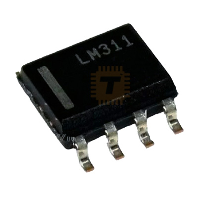
| Name | Original LM311 Voltage Comparator IC SOIC-8 |
| Code | IC0336 |
| Price | Rs.50.00 |
| In Stock | Yes |
| Package | SMD |
Product Details
The LM311 is a highly versatile, high-speed voltage comparator designed to operate over a wide range of supply voltages. Unlike standard operational amplifiers used as comparators, the LM311 features a unique output stage that is functionally independent of the supply voltage. This allows it to interface directly with TTL, CMOS, and RTL logic, as well as drive lamps or relays up to 50V.
Specifications
- Supply Voltage: 5V to 15V (Dual) or up to 36V (Single)
- Response Time: 200nS (Typical)
- Maximum Output Current: 50mA
- Input Bias Current: 250nA (Max)
- Input Offset Current: 50nA (Max)
- Package: SOIC-8 (Surface Mount)
Features
- Flexible Output Stage: Features an "open-collector" output (collector and emitter are both available on pins). This allows the load to be referenced to ground, Vcc, or even a separate external power supply.
- High Drive Capability: Can sink up to 50mA of current, which is sufficient to directly drive small relays, LED indicators, or switching transistors.
- Wide Input Range: The differential input voltage can be as high as ±30V, regardless of the supply voltage used.
- Strobe/Balance Capability: Includes pins for offset balancing and a "strobe" function, which can be used to disable the output regardless of the input signal.
- Low Power Consumption: Designed for high efficiency without sacrificing switching speed.
Common Applications
- Zero-Crossing Detectors: Converting sine waves into square waves for timing and frequency measurements.
- Level Detectors/Alarms: Triggering a signal when a sensor voltage exceeds a specific reference.
- Window Comparators: Detecting if a signal is within a specific voltage "window" (requires two LM311s).
- Pulse Generators: Creating precise timing pulses for clocking circuits.
- Relay Drivers: Driving a magnetic relay directly from an analog threshold.
Usage Tips
- Pull-Up Resistor: Because the output is open-collector, you must use a pull-up resistor (typically 1k to 10k) connected between Pin 7 and your desired logic voltage (e.g., 5V or 3.3V) to see a high signal.
- Hysteresis: To prevent "chattering" or oscillation when the input signal is noisy or moves slowly near the threshold, add a high-value feedback resistor (e.g., 1M) from the output to the non-inverting input.
- Grounding: Pin 1 (Emitter Out) does not necessarily have to go to ground, but it must be more negative than Pin 7 (Collector) for the output transistor to function.
- Decoupling: Standard 0.1uF ceramic capacitors should be placed near the supply pins to maintain speed and minimize switching noise on the supply lines.
Sharing is caring, show love and share the product with your friends.
Featured

Add to Cart

Add to Cart
Other Products
Add to Cart