Original Microchip PIC12F1572 PDIP-8 (MC0001) Products
| Name | Original Microchip PIC12F1572 PDIP-8 |
| Code | MC0001 |
| Price | Rs.630.00 |
| In Stock | Yes |
| Package | SOIC-28 |
Product Details
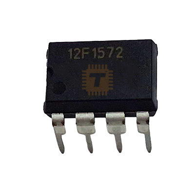
The Original Microchip PIC12F1572 8-Bit Flash Microcontroller is an ultra-compact, high-performance 8-pin MCU manufactured by Microchip Technology. Encapsulated in a prototyping-friendly standard PDIP-8 (DIP-8) through-hole package, it is powered by an enhanced mid-range 8-bit core operating at speeds up to 32 MHz (with a precision internal oscillator). The PIC12F1572 is specifically distinguished by its three independent 16-bit PWM modules with dedicated complementary waveform generators (CWG) and phase-shifting capabilities, making it an ideal choice for high-precision LED lighting (RGB/RGBW), precision motor control, power conversion, and general-purpose embedded applications. Additionally, it integrates a hardware EUSART interface, a 10-bit ADC, a 5-bit DAC, an analog comparator, and Core Independent Peripherals (CIPs) to offload timing-critical tasks from the central processor.
Specifications
- Part Number / Model: PIC12F1572-I/P / PIC12F1572 (Industrial Temperature Grade)
- Manufacturer: Microchip Technology
- Core Architecture: Enhanced Mid-Range 8-Bit PIC Core (49 Instructions)
- Package Type: PDIP-8
- Operating Voltage Range (VDD): 2.3V to 5.5V DC (Wide operating supply range)
- Maximum CPU Operating Frequency: Up to 32 MHz (via internal 4x PLL / external clock source)
- Internal Oscillator: Factory-calibrated High-Frequency Internal Oscillator (HFINTOSC) from 31 kHz to 32 MHz (±1% typical accuracy)
- Program Memory (Flash): 3.5 KB (2,048 Words Flash Program Memory, Self-Read/Write capability)
- Data SRAM: 256 Bytes
- Data EEPROM / HEF: 128 Bytes High-Endurance Flash (HEF) memory (100k write cycles)
- I/O Pins: 6 General Purpose I/O Pins (5 I/O + 1 Input-Only Pin RA3/MCLR)
- High-Resolution PWMs: 3 Independent 16-bit PWM Generators (with offset, phase, and duty cycle control)
- Complementary Waveform Generator (CWG): 1 Hardware Module with programmable dead-band delay and auto-shutdown
- Analog-to-Digital Converter (ADC): 10-Bit ADC with 4 Input Channels and internal Fixed Voltage Reference (FVR)
- Digital-to-Analog Converter (DAC): 1x 5-Bit Rail-to-Rail Resistive DAC
- Analog Comparator: 1 Low-Power / High-Speed Rail-to-Rail Comparator
- Serial Communication: 1 Enhanced Universal Synchronous/Asynchronous Receiver/Transmitter (EUSART with LIN / DMX support)
- Timers:
- Timer0: 8-Bit Timer/Counter with 8-bit prescaler
- Timer1: 16-Bit Timer/Counter with dedicated low-power 32.768 kHz gate/oscillator
- Timer2: 8-Bit Timer with 8-bit Period Register, prescaler, and postscaler
- Power Management (nanoWatt XLP): Extreme Low-Power modes (Sleep current < 20nA>
- Operating Ambient Temperature (TA): -40°C to +85°C (Industrial Grade)
- Storage Temperature Range (Tstg): -65°C to +150°C
- Pinout Configuration (PDIP-8):
- Pin 1: VDD (Positive Power Supply Input, +2.3V to +5.5V)
- Pin 2: RA5 (General Purpose I/O / T1CKI / OSC1 / CLKIN / PWM1)
- Pin 3: RA4 (General Purpose I/O / AN3 / T1G / OSC2 / CLKOUT / PWM2)
- Pin 4: RA3 / MCLR / VPP (Input Only / Active-Low Master Clear Reset / Programming Voltage)
- Pin 5: RA2 (General Purpose I/O / AN2 / INT / CWG1OUTA / DAC1OUT / PWM3)
- Pin 6: RA1 / ICSPCLK (General Purpose I/O / AN1 / RX / DT / In-Circuit Serial Programming Clock)
- Pin 7: RA0 / ICSPDAT (General Purpose I/O / AN0 / TX / CK / In-Circuit Serial Programming Data)
- Pin 8: VSS (Ground / 0V Reference)
Features
- Triple 16-Bit High-Resolution PWMs: Features 16-bit PWM modules capable of high-precision duty cycle, phase shift, and offset adjustments, ideal for multi-channel RGBW LED stage lighting, dimming, and custom SMPS generation.
- Complementary Waveform Generator (CWG): Generates non-overlapping complementary switching signals with programmable rising and falling edge dead-band delays to safely drive half-bridge MOSFET drivers without shoot-through risk.
- On-Chip Hardware EUSART: Full hardware serial UART peripheral supports standard RS-232/RS-485, DMX512 lighting control, and LIN protocols up to high baud rates without software bit-banging overhead.
- Core Independent Peripherals (CIPs): Hardware peripherals operate independently of the CPU core, maintaining critical timings and safety shutdowns even when the processor is in deep sleep.
- nanoWatt XLP Technology: Ultra-low active and sleep power consumption allows multi-year operation from small lithium coin cells (CR2032) or battery backups.
- Flexible PDIP-8 Through-Hole Footprint: Standard 0.1-inch (2.54mm) pitch DIP package is directly compatible with solderless breadboards, IC sockets, and DIY proto-boards.
Common Applications
- High-Resolution LED Lighting & Stage Fixtures: Precision 16-bit color mixing for RGB/RGBW architectural fixtures, mood lights, and DMX512 receivers.
- DC Motor & Servo Control: Precise speed and direction control for brushed DC motors, fans, and RC actuators.
- Switched-Mode Power Supply (SMPS) Controllers: Generating synchronous switching signals with dead-time for small buck, boost, and flyback converters.
- Intelligent Sensor Nodes: Sampling analog transducers via the 10-bit ADC and transmitting data over UART/LIN buses.
- Automotive & Appliance Sub-Controllers: Small dedicated auxiliary control, keypad decoders, and timer delay modules.
Usage Tips
- In-Circuit Serial Programming (ICSP): For programming and debugging using Microchip PICkit (PICkit 3, 4, 5) or SNAP debuggers, connect:
- VPP/MCLR to Pin 4 (RA3)
- VDD (+3.3V or +5.0V) to Pin 1
- VSS (GND) to Pin 8
- ICSPDAT to Pin 7 (RA0)
- ICSPCLK to Pin 6 (RA1)
- Power Supply Decoupling: Place a **0.1µF (100nF) ceramic capacitor** directly across Pin 1 (VDD) and Pin 8 (VSS) with the shortest possible trace length to ensure reliable microcontroller operation and ADC accuracy.
- MCLR Pin Configuration: If Pin 4 (RA3) is configured in firmware configuration bits as a General-Purpose Input (MCLRE = OFF), it cannot be used as an output. If used as an active-low reset pin (MCLRE = ON), pull Pin 4 up to VDD through a **10kΩ resistor** (with an optional 100nF capacitor to GND for noisy environments).
- UART Pin Sharing with ICSP: Note that the hardware UART pins (TX on RA0, RX on RA1) share lines with ICSPDAT and ICSPCLK. Isolate high-current loads or strong pull-ups/pull-downs from Pins 6 and 7 during in-circuit firmware flashing.
- Internal Fixed Voltage Reference (FVR): When reading ratiometric or battery voltages with the 10-bit ADC, enable the built-in FVR (configurable to 1.024V, 2.048V, or 4.096V) as the ADC positive reference ($V_{REF+}$) to achieve stable ADC conversions independent of VDD fluctuations.
Sharing is caring, show love and share the product with your friends.
Featured

Add to Cart

Add to Cart


Add to Cart