Original SG3525AN Regulating Pulse Width Modulators DIP-16 (IC0349) Products
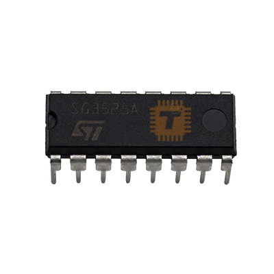
| Name | Original SG3525AN Regulating Pulse Width Modulators DIP-16 |
| Code | IC0349 |
| Price | Rs.230.00 |
| In Stock | Yes |
| Package | DIP-16 |
Product Details
The Original SG3525AN Regulating Pulse Width Modulator is an industry-standard integrated pulse-width modulation (PWM) control IC manufactured by STMicroelectronics / ON Semiconductor. Encapsulated in a standard DIP-16 through-hole package, it is designed to deliver improved performance and reduced external parts count in all types of switch-mode power supplies (SMPS). Operating over a wide input supply range of 8V to 35V, the SG3525AN features an on-chip precision 5.1V trimmed reference (±1%), an integrated linear sawtooth oscillator capable of switching frequencies up to 400 kHz, a wide-bandwidth error amplifier, dual totem-pole output drivers capable of sourcing/sinking up to 500mA peak current, programmable dead-time control, soft-start circuitry, and comprehensive shutdown protection. It is widely utilized in high-frequency push-pull, half-bridge, and full-bridge DC-DC converters, solar inverters, and switch-mode power supplies.
Specifications
- Part Number / Model: SG3525AN (Direct replacement for standard SG3525A series)
- Device Function: Pulse Width Modulation (PWM) Controller for Switching Regulators
- Package Type: DIP-16 (Dual In-Line 16-Pin Through-Hole)
- Supply Voltage Range (Vcc / Pin 15): 8.0V to 35V DC
- Collector Supply Voltage (Vc / Pin 13): 4.5V to 35V DC
- Reference Output Voltage (Vref / Pin 16): Typ. 5.10V / Range 5.00V to 5.20V (±1% initial tolerance)
- Oscillator Frequency Range: 100 Hz to 400 kHz (Programmed via external RT and CT)
- Output Driver Current (Pins 11 & 14): Continuous: 100mA / Peak Sourcing & Sinking: 500mA
- Output Topology: Dual Totem-Pole (Push-Pull complementary active-high drivers)
- Error Amplifier Input Common-Mode Voltage: 1.5V to (Vcc - 2.5V)
- Error Amplifier Open-Loop Gain: Typ. 75 dB / Min. 60 dB
- Error Amplifier Unity Gain Bandwidth: Typ. 1.0 MHz to 2.0 MHz
- Deadtime Range (Set by RD / Pin 7): 0.5µs to 5.0µs
- Soft-Start Source Current (Pin 8): Typ. 50µA / Min. 25µA
- Shutdown Input Voltage Threshold (Pin 10): Typ. 0.7V / Range 0.6V to 0.8V
- Undervoltage Lockout (UVLO) Threshold: Typ. 7.0V (Turn-on threshold 8.0V max, hysteresis ~0.8V)
- Total Quiescent Operating Current: Typ. 14mA / Max. 20mA
- Power Dissipation (Pd): 1000mW (at Ta = 25°C)
- Operating Ambient Temperature Range (Ta): 0°C to +70°C
- Storage Temperature Range (Tstg): -65°C to +150°C
- Thermal Resistance, Junction to Ambient (Rth(j-a)): 80°C/W to 100°C/W
- Pinout Configuration:
- Pin 1: Inverting Input (Inv. In)
- Pin 2: Non-Inverting Input (Non-Inv. In)
- Pin 3: Oscillator Sync (Sync)
- Pin 4: Oscillator Output (OSC Out)
- Pin 5: Timing Capacitor (CT)
- Pin 6: Timing Resistor (RT)
- Pin 7: Discharge / Deadtime Resistor (RD)
- Pin 8: Soft-Start (SS)
- Pin 9: Compensation / Output of Error Amp (Comp)
- Pin 10: Shutdown (SD)
- Pin 11: Output A (Out A)
- Pin 12: Ground (GND)
- Pin 13: Collector Voltage Supply (Vc)
- Pin 14: Output B (Out B)
- Pin 15: Input Operating Supply (Vcc)
- Pin 16: Reference Voltage Output (+5.1V Vref)
Features
- Trimmed Precision 5.1V Reference: Built-in high-accuracy on-chip reference eliminates the need for external precision voltage regulators to bias the feedback network.
- Dual High-Current Totem-Pole Outputs: Integrated push-pull output drivers deliver up to 500mA peak, capable of driving power MOSFET gates or gate-drive transformers directly without external buffer transistors.
- Programmable Deadtime Control: Adding a resistor between Pin 5 (CT) and Pin 7 (Discharge) allows precise dead-time adjustment to eliminate shoot-through current in bridge topologies.
- Built-in Soft-Start Functionality: Connecting a single capacitor from Pin 8 (Soft-Start) to Ground provides smooth, linear ramp-up of duty cycle during power-on, preventing transformer saturation and high inrush currents.
- Wide Oscillator Operating Range: Dual-polarity linear sawtooth ramp generator operates cleanly from 100Hz up to 400kHz, allowing optimization for compact magnetic transformer designs.
- Fast Over-Current Shutdown: Dedicated active-high shutdown input (Pin 10) provides cycle-by-cycle current limiting or latching shutdown with immediate discharge of the soft-start capacitor.
Common Applications
- Push-Pull & Full-Bridge DC-DC Converters: High-efficiency step-up converters in 12V/24V to 220V/310V inverter driver boards.
- Solar Inverters & UPS Power Stages: Primary-side PWM switching drivers in online pure sine wave and modified sine wave inverters.
- High-Frequency Induction Heaters: Precise frequency generation and complementary gate drive for resonant inverter tanks.
- Switch-Mode Power Supplies (SMPS): Half-bridge and forward converter main control topologies in industrial telecom power supplies.
- High-Power DC Motor Controllers: H-bridge PWM speed regulation and industrial variable torque drives.
Usage Tips
- Separate Vcc and Vc for Gate Drive Optimization: Pin 15 supplies power to internal logic/oscillator circuits, while Pin 13 (Vc) feeds the output totem-pole stages; you can connect Pin 13 to a separate 12V–15V rail to ensure optimal Vgs drive voltage for external N-channel MOSFETs.
- Oscillator Calculation Formula: Set the switching frequency using the timing components: f_osc ≈ 1 / [CT × (0.7 × RT + 3 × RD)]. Keep RT between 2kΩ and 150kΩ, CT between 1nF and 100nF, and RD between 0Ω and 500Ω.
- Decoupling the 5.1V Reference: Always place a 100nF low-ESR ceramic capacitor directly between Pin 16 (Vref) and Pin 12 (GND) to suppress high-frequency noise that could cause PWM jitter.
- Soft-Start Capacitor Sizing: Use a 1µF to 10µF electrolytic or tantalum capacitor on Pin 8 to achieve smooth startup ramp times (typically 100ms to 500ms), protecting external power switches from destructive turn-on surge currents.
- Gate Resistors: When directly driving power MOSFETs from Pins 11 and 14, install 10Ω to 22Ω series gate resistors to damp parasitic gate ringing and protect the internal totem-pole transistors from capacitive switching spikes.
Sharing is caring, show love and share the product with your friends.
Featured


Add to Cart