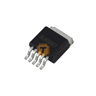
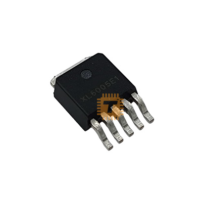
Original XL6005E1 Buck DC-DC Converter IC TO-263-5L (IC0345) Products
Name
Original XL6005E1 Buck DC-DC Converter IC TO-263-5L
Code
IC0345
Price
Rs.150.00
In Stock
Yes
Package
THT
Product Details
The XL6005E1 is a fixed-frequency, current-mode step-up (Boost) regulator optimized specifically for driving high-brightness LEDs in series. By integrating a high-voltage power NMOS transistor inside the silicon die, the chip eliminates the need for an external switching transistor, drastically simplifying power supply design. The regulator features a very low feedback threshold voltage (0.22V), which drastically reduces power dissipation across the current-sensing resistor, maximizing overall system efficiency.
Specification
Manufacturer: XLSEMI
Package Form Factor: TO-263-5L (Surface-mount with 5 pins and a thermal metal tab)
Topology: Boost (Step-Up) Constant Current
Input Operating Voltage Range (VIN): 3.6V to 32V
Maximum Output/Switching Voltage: Up to 60V
Maximum Internal Switching Current Limit (ISW): 4A
Fixed Switching Frequency: 180 kHz (± 20%)
Feedback Reference Voltage (VFB): 220mV (Adjustable via sensing layout)
Internal Power NMOS RDS(ON): approx 110 mΩ
Maximum Duty Cycle: 90%
Conversion Efficiency: Up to 94%
Safety Protections: Built-in Short-Circuit, Thermal Shutdown, and Over-Current Limit
Features
High-Power Series LED Capability: At an input voltage of VIN ≥ 12V, the chip’s boost structure can seamlessly string together and drive up to 11 series-connected 1W LEDs simultaneously without blinking.
Ultra-Low Reference Voltage (0.22V): Traditional adjustable regulators rely on a 1.25V feedback pin, which wastes energy as heat at high currents. The XL6005E1 uses a tiny 0.22V loop, keeping energy conversion cool and compact.
Dual-Function Enable (EN) Pin: The EN pin accepts standard TTL logic inputs. Grounding this pin forces the chip into a complete shutdown state drawing under 100μA. Alternatively, applying a low-frequency PWM signal to this pin allows for smooth, flicker-free dimming arrays.
Minimal Component Blueprint: Thanks to integrated internal loop frequency compensation and a built-in soft-start routine, a complete circuit requires only an input/output capacitor, a boost inductor, a Schottky diode, and a small current-sense resistor.
Common Applications
High-Power LED Industrial Lighting: Powering commercial spotlights, stage lamps, and high-efficiency automotive lighting matrices.
Display Backlighting Assemblies: Driving large-scale LED backlighting string arrays for 7-inch to 15-inch LCD panels and video monitors.
Solar-Powered LED Systems: Stepping up 6V or 12V solar battery storage banks to high-voltage strings for outdoor municipal street lighting.
Portable Battery Boosters: Converting low-voltage Lithium-ion or multi-cell AA battery setups to stable higher voltage rails for mobile electronics.
Professional Usage & Deployment Tips
Select a High-Saturation Inductor: Do not size the boost inductor based solely on the continuous output LED current. Because it is a boost topology, the peak switching current passing through the inductor can reach up to the 4A device limit under heavy loads. Select a power inductor (typically 33 μH to 68 μH) with a physical saturation current (Isat) rating of at least 4.5A to prevent core saturation, which will cause massive heating and catastrophic efficiency loss.
Calculate the Current Sensing Resistors Accurately: The LED string current (ILED) is set by choosing a precise shunt resistor (RSET) bridging the FB pin to Ground. Use the equation:
RSET = 0.22V/ ILED
For example, to drive standard 1W LEDs at a stable 350mA (0.35A), deploy a highly accurate 0.63Ω resistor rated for at least 0.5W of thermal dissipation.
Implement Open-LED Protection: If an LED in the series string goes open-circuit or fails, a boost converter will continuously pump up the output voltage attempting to reach its target current until the internal 60V switch explodes. To protect the IC, always wire a Zener diode across the output loop (in series with a resistor leading to the FB pin). Select a Zener voltage rated at roughly 1.3 times the maximum string voltage to clamp the loop safely if a connection snaps.
Thermal Layout Management: The TO-263-5L package transfers heat directly through its large metal tab. Solder the tab down to a large, unbroken copper pour zone on the PCB (ideally connected to internal layer planes using stitched thermal vias). Poor heat sinking will trigger the chip's internal thermal protection boundary (125℃), causing the current driver to constantly scale down power or oscillate off.