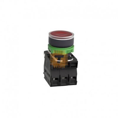
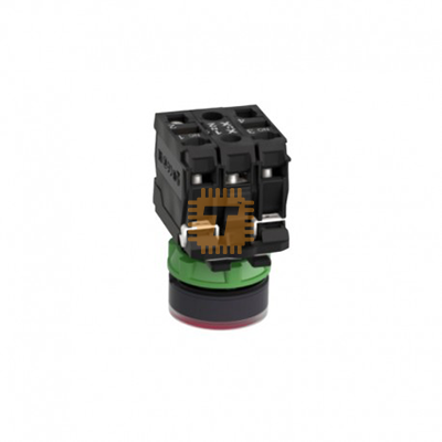
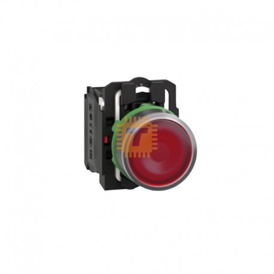
Schneider Electric XB5AW34B5C Red Indicator Push Button Panel Mount (TA1878) Products
Name
Schneider Electric XB5AW34B5C Red Indicator Push Button Panel Mount
Code
TA1878
Price
Rs.2,300.00
In Stock
Yes
Package
PANEL
Product Details
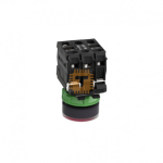
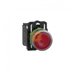
The Schneider Electric XB5AW34B5C is a complete 22mm panel-mounted, red illuminated push-button assembly from the Harmony XB5 plastic series. Combining a double-insulated plastic operator head with an integrated 24V protected LED light block and a dual contact arrangement (1 NO + 1 NC), it serves as a human-machine interface element for switching, status indication, and safety interlocks.
Mechanical Durability: Up to 10,000,000 operations
Operating Temperature: -40°C to +70°C
Features
Double-Insulated Plastic Body: Built using high-impact dark grey plastic bezels and fixing collars, offering corrosion resistance against chemical agents, water washdowns, and electrical shock risks without requiring a grounding wire on the bezel.
Dual Contact Switching (1 NO + 1 NC): Includes both a Normally Open (13 - 14) and Normally Closed (21 - 22) slow-break contact block out of the box. This enables simultaneous control actions—such as shutting down a run circuit via NC while triggering an alarm/fault signal via NO.
Integrated 24V LED Light Source: Powered by a long-life LED module (100,000 hours service life) operating on 24V AC/DC control voltage, producing a bright red visual indicator visible from a distance.
Extreme Environmental Sealing (IP69K): Rated up to IP66 / IP67 / IP69K and NEMA 4X, making it suitable for food and beverage processing, marine, chemical, or outdoor control boxes subjected to hot high-pressure hose-downs.
Common Applications
Machine Stop / Fault Reset Buttons: Used as a prominent red stop or fault acknowledge button where a visual red indicator confirms system power or fault status.
Process Interlocking & Safety Isolation: Simultaneously opening a operational control circuit (21 - 22 NC) while engaging a secondary monitoring loop (13 - 14 NO).
Industrial Control Cabinets: Installed across standard 22mm control enclosures, motor control centers (MCCs), and outdoor pump control panels.
Installation & Wiring Guide
Panel Cutout Prep: Punch a standard 22.5mm mounting hole into the enclosure door.
Mount Operator Head: Push the red illuminated operator head through the front face of the cutout.
Attach Fixing Collar: Slide the plastic fixing collar onto the back of the head from inside the panel and tighten the locking screw (0.8-1.2N.m).
Wire Contact Blocks:
Terminals 13 - 14 (NO): Wire into your auxiliary monitoring or alarm circuit.
Terminals 21 - 22 (NC): Wire into your primary motor or coil run circuit.
Wire LED Block (X1 - X2): Connect your 24V AC/DC supply leads to the central light module terminals marked X1 (+) and X2 (-).
Sharing is caring, show love and share the product with your friends.