4 Channel 433MHz Remote Controller with 4 Way 12VDC 3A Relay Module (MD0985) Products
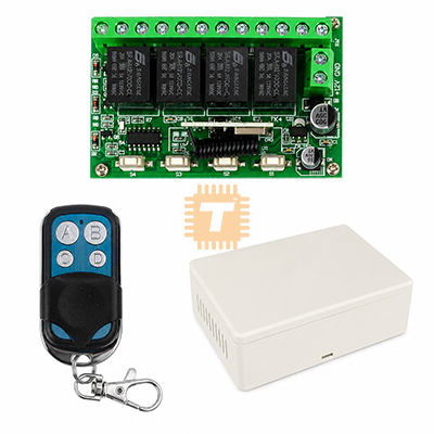
| Name | 4 Channel 433MHz Remote Controller with 4 Way 12VDC 3A Relay Module |
| Code | MD0985 |
| Price | Rs.2,400.00 |
| In Stock | Yes |
| Package | MODULE |
Product Details
The 4 Channel 433MHz Remote Controller with 4 Way 12VDC 3A Relay Module is a versatile, industrial-grade wireless switching solution engineered for long-range actuation of home automation devices, motorized garage doors, security gates, linear actuators, and lighting systems. Operating on the license-free 433.92 MHz ISM band, this transmitter-receiver pair utilizes EV1527/PT2262 learning code decoding to ensure secure, interference-resistant signal transmission across open-air distances up to 50–100 meters. The 4-channel receiver board integrates independent, optocoupler-isolated electromechanical relays featuring Form C (SPDT: NO/COM/NC) dry contacts rated for both DC (up to 12V/3A–10A) and AC mains (up to 250V AC) loads, with easily selectable Momentary, Toggle (Self-locking), and Latching (Interlocking) working modes.
Specifications
- Operating RF Frequency: 433.92 MHz (±75 kHz)
- Modulation Method: ASK / OOK (Amplitude Shift Keying)
- RF Encoding Scheme: EV1527 Learning Code (Supports Fixed Code PT2262 / 2260 compatibility)
- Receiver Working Voltage: 12.0 V DC (±10% Regulated DC Input)
- Receiver Quiescent / Standby Current: ≤ 6 mA to 10 mA
- Receiver Active Current: Approx. 120 mA to 160 mA (All 4 relays energized simultaneously)
- Receiver Sensitivity: -105 dBm (Superheterodyne / Super-regenerative receiver stage)
- Relay Output Channels: 4 Independent Channels (SPDT Form C: Normally Open, Common, Normally Closed)
- Contact Rating per Relay:
- DC Load: 3 A to 10 A at 12 V to 30 V DC
- AC Load: Up to 10 A at 125 V / 250 V AC (Resistive load)
- Selectable Operating Modes: Momentary (Jog), Toggle (Self-Locking), and Latching (Interlocked) via Onboard Learn Button / Jumper Header
- Storage Capacity: Supports up to 16 to 20 remote transmitters in internal EEPROM
- RF Transmission Distance: Approx. 50 m to 100 m (164 ft to 328 ft open-field line of sight)
- Transmitter Power Supply: 12 V Alkaline Battery (Type 27A or 23A) or 3 V CR2032 Coin Cell (Remote model dependent)
- Transmitter RF Output Power: Approx. 10 mW to 15 mW
- Terminal Connections: Industrial Screw Terminal Blocks (Accommodates 24 AWG to 14 AWG wire)
- Antenna Configuration: Helical spring wire antenna or external wire lead (50 Ω impedance)
- Operating Ambient Temperature: -20°C to +70°C (-4°F to 158°F)
- Receiver Board Dimensions: Approx. 68 mm × 48 mm × 19 mm
- Protective Housing: Snap-fit white/black ABS flame-retardant enclosure
- Net Weight: Approx. 85 g to 110 g (Receiver board, housing, and handheld remote combined)
Pinout & Terminal Definition
- DC Power Supply Input Terminals:
- Terminal V+ / +12V: Connects to +12 V DC Power Supply Positive rail
- Terminal V- / GND: Connects to Power Supply Negative rail / Ground (0 V)
- Relay Output Terminals (Channels 1 to 4):
- Terminal NO (Normally Open): Disconnected from COM when idle; connects to COM when relay is energized
- Terminal COM (Common): Main movable contact terminal / Switched circuit common feed
- Terminal NC (Normally Closed): Connected to COM when idle; opens/disconnects when relay is energized
- Control Interface:
- Learning Button (KEY): Used for clearing memory and pairing operating modes
- LED Indicator: Visual feedback for RF packet reception, programming confirmation, and reset states
Features
- Flexible 3-in-1 Operating Modes: Easily configurable between Momentary (holds while button is pressed), Toggle (press on, press off), and Latching (one button on turns others off) without external firmware reprogramming.
- Complete Electrical Isolation: Electromechanical dry relay contacts isolate low-voltage microcontroller/receiver logic from high-voltage AC mains or inductive motor lines, preventing ground loops and electrical interference.
- EEPROM Learning Code Retention: Stores paired transmitter RF codes permanently in non-volatile memory, maintaining pairing through sudden power outages or power cycles.
- Simultaneous Multi-Channel Control: Capable of actuating all 4 channels independently or simultaneously, allowing complex automation routines such as multi-axis direction control or zone switching.
- Protective Shell & Screw Terminals: Encased in an insulated ABS project shell with heavy-duty screw terminals for fast, solder-free field wiring.
Common Applications
- Access Control & Barriers: Wireless opening and closing of motorized rolling shutters, sliding driveway gates, and garage doors.
- Smart Home & Lighting: Remote actuation of interior/exterior LED lighting fixtures, garden floodlights, landscape water pumps, and ventilation exhaust fans.
- Motor & Actuator Control: Direction control (forward, reverse, stop) for 12V DC linear actuators, winch motors, and motorized TV lift brackets.
- Industrial Equipment Automation: Wireless emergency stop signaling, remote conveyor motor switching, and workshop dust collector activation.
- Automotive & Marine Accessories: Operating auxiliary 12V LED lightbars, boat bilge pumps, remote horns, and motorized anchor hoists.
Usage Tips
- Pairing and Mode Selection Procedure (CRITICAL):
- Momentary Mode: Press the receiver's learning button 1 time → Wait for the LED to illuminate solid → Press any button on the remote. The LED flashes and turns off (Relay activates only while remote key is held down).
- Toggle Mode: Press the learning button 2 times → Wait for the LED to illuminate → Press any remote button. The LED flashes and turns off (Pressing the button once turns relay ON; pressing again turns it OFF).
- Latching Mode: Press the learning button 3 times → Wait for the LED to illuminate → Press any remote button. The LED flashes and turns off (Button A turns Channel 1 ON and shuts other channels OFF).
- Clearing All Codes: Press the learning button 8 consecutive times. The LED will flash rapidly, wiping all saved remote keys from internal memory.
- Inductive Load Snubber / Protection: When switching high-inductance DC loads (e.g., 12V solenoids, linear actuators, or DC motors), connect a 1N4007 flyback diode in reverse-bias directly across the load terminals to suppress inductive voltage kickback that can pit the relay contacts or trigger receiver lockup.
- Antenna Optimization: For maximum operational range, fully uncoil and straighten the onboard copper spiral antenna into a vertical wire orientation (ideal resonant length: ~17.3 cm, which represents a quarter-wavelength λ/4 at 433 MHz). Keep the antenna clear of metal framing or grounded enclosures.
- Power Supply Cleanliness: Use a well-filtered, regulated 12V DC power adapter (minimum 1A output). High-frequency ripple from poor-quality switch-mode wall adapters can degrade receiver RF sensitivity and reduce range.
- Contact Rating Limits: Although relays may list 10A ratings on their plastic cases, maintain continuous loads below 3A to 5A when installed inside the closed plastic enclosure to prevent internal heat buildup and ensure long contact life.
Sharing is caring, show love and share the product with your friends.
Featured


Other Products
Add to Cart
Add to Cart