
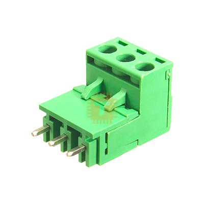
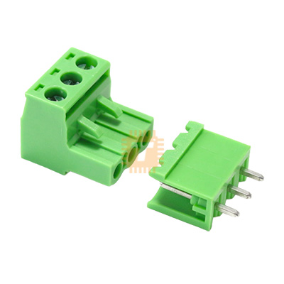
5.08mm Pitch 3-Pin 3-way Straight Pluggable Screw Terminal Block PCB Mount (TB0057) Products
| Name | 5.08mm Pitch 3-Pin 3-way Straight Pluggable Screw Terminal Block PCB Mount |
| Code | TB0057 |
| Price | Rs.50.00 |
| In Stock | Yes |
| Package | THT |
Product Details
This 5.08mm pitch 3-pin pluggable screw terminal block is a heavy-duty, two-piece electrical connector set designed for secure, detachable wire-to-board connections on printed circuit boards (PCBs). The system consists of a straight, vertical male header block soldered directly to the board, and a mating female plug piece outfitted with secure rising-cage screw terminals. This pluggable design enables swift field maintenance, easy upgrades, and rapid hardware hot-swaps without requiring desoldering irons or wire re-stripping.
Specification
- Pitch (Pin Spacing): 5.08mm (approx 0.2 inches)
- Pin / Way Count: 3-Pin / 3-Way
- Orientation: Straight / Vertical (90°C relative to the PCB surface)
- Voltage Rating: Up to 300V AC/DC
- Current Capacity: 10A to 15A continuous (depending on wire gauge)
- Wire Stripping Gauge Range: 12 AWG to 24 AWG (Accepts solid or stranded wires)
- Screw Mechanism: M2.5 or M3 steel screws with zinc plating (utilizes a rising-clamp box system)
- Insulation Material: High-temperature Polyamide (PA66), UL94V-0 rated flame retardant
- Contact Flanges: Tin-plated phosphor bronze pins for low surface resistance
- Color: Industry Standard Green
Features
- Two-Piece Pluggable Architecture: The male header is permanently anchored to the PCB, while the female wire housing features a smooth disconnect track. This allows technicians to disconnect full multi-wire wiring harnesses in a single motion during system servicing.
- Robust Rising Cage Clamp Mechanism: Rather than pushing a spinning screw directly into wire copper strands—which can sever or fray the conductor—the screw pulls an internal metal elevator clamp upwards. This clamps the wire uniformly over a wide surface area, preventing damage to thin, stranded wiring.
- Interlocking Modular Side Walls: The connector housings are molded with side slots and tabs, enabling individual blocks to be slid and snapped together to cleanly form custom continuous configurations (e.g., combining a 2-pin and a 3-pin block to create a 5-pin terminal array).
- Industry Standard 5.08mm Grid Alignment: The 5.08mm spacing perfectly matches standard prototype breadboards, stripboards, and electronic CAD layout footprints, allowing trouble-free drop-in integration on new board spins.
Common Applications
- Industrial Automation & PLC Modules: Routing DC input power lines, Modbus/RS485 communication pairs, and multi-channel sensor signals to control modules.
- Power Supply Outputs & Converters: Serving as high-current attachment ports on custom buck/boost converters, transformer break-out boards, and distribution bars.
- DIY Robotics & Motor Controllers: Providing clean, robust connection points for high-current stepper motor windings, brushed DC motor lines, and main battery input leads.
- Smart Home Devices & HVAC Controllers: Interfacing main thermostat control wires, relay lines, and ambient sensor arrays inside distribution panel boxes.
Professional Usage & Integration Tips
- Use Bootlace Ferrules for Stranded Wires: While the rising cage system handles bare stranded wire safely, fine copper strands can occasionally splay outward during tight installation twists, risking a minor short-circuit to adjacent pins. Always crimp standard bootlace ferrules onto stranded wires before insertion to shield the conductor and ensure long-term mechanical reliability.
- Design Proper PCB Trace Widths: Do not limit your PCB layout paths to thin default trace widths if you plan to push the full 10A - 15A rating through the terminal block. Use thick copper pours (e.g., 2 oz/ft² copper weight) and widen your paths appropriately to manage thermal trace rise.
- Apply Appropriate Screw Torque: Tighten the terminal screws firmly but avoid excessive force. Over-torquing with an oversized flathead screwdriver can strip the internal brass threads or fracture the PA66 plastic header wall. Use a precision 2.5mm jeweler's screwdriver for optimal torque control.
- Provide Clearance for Structural Mating: When drafting your electronic enclosure layout, remember that the wire-entry plug extends outward beyond the header profile. Leave a clear gap of at least 15-20mm directly in front of the terminal block to allow fingers or tools to comfortably plug/unplug the terminal array and route exiting wires safely without harsh bending strains.
Sharing is caring, show love and share the product with your friends.
Featured

Add to Cart

Add to Cart


Other Products
Add to Cart
Add to Cart
Add to Cart
