ACS712 5A Current Sensor Module for Arduino (MD0044) Products


| Name | ACS712 5A Current Sensor Module for Arduino |
| Code | MD0044 |
| Price | Rs.300.00 |
| In Stock | Yes |
| Package | MODULE |
Product Details
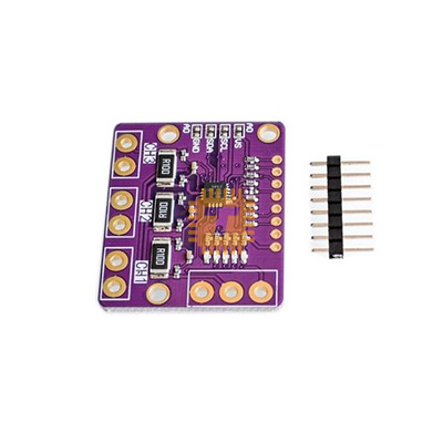
The ACS712 5A is a fully integrated, Hall-effect-based linear current sensor designed for accurate AC or DC current sensing. It provides a low-interference, economical solution for current monitoring in industrial, commercial, and communications systems. Because it uses a Hall-effect sensor, the module provides electrical isolation between the high-current path and the low-voltage electronics (like your Arduino), ensuring safety and circuit protection.
Specifications
- Supply Voltage (VCC): 4.5V – 5.5V DC
- Measurement Range: -5A to +5A (Bi-directional)
- Sensitivity: 185mV/A (Typical)
- Output Voltage at 0A: VCC / 2 (Typically 2.5V)
- Total Output Error: 1.5% at T_A = 25C
- Internal Conductor Resistance: 1.2 MOhm
- Isolation Voltage: 2.1 kVRMS
Working Principle
The current to be measured flows through the module’s onboard copper conduction path. This current generates a magnetic field which is sensed by the integrated Hall IC and converted into a proportional linear voltage.
Features
- Bi-directional Sensing: The sensor can measure both positive and negative current. On a 5V supply, the output stays at 2.5V when no current is flowing; it rises toward 5V for positive current and drops toward 0V for negative current.
- Electrical Isolation: The terminals of the conductive path are electrically isolated from the sensor leads. This allows the sensor to be used in high-side applications without needing additional isolators.
- Low-Noise Analog Path: Features a high-bandwidth analog signal path with an 80kHz bandwidth, making it suitable for motor control and power monitoring.
- Minimal Power Loss: The very low internal resistance (1.2 MOhm of the copper path ensures that the sensor itself consumes very little power and does not significantly drop the voltage of the load.
- Simple Analog Interface: The output is a simple DC voltage proportional to the current, which can be connected directly to any microcontroller's ADC pin.
Pin Configuration
- Input (Screw Terminals):
- Terminal 1 & 2: Connected in series with the load you wish to measure.
- Output (3-Pin Header):
- VCC: 5V Power Supply.
- OUT: Analog Signal Output.
- GND: Ground.
Common Applications
- Over-Current Protection: Detecting faults in motor circuits or power supplies.
- Battery Chargers: Monitoring the charging rate and state of health for battery packs.
- Smart Energy Meters: Calculating power consumption in DIY Watt-meter projects.
- Solar Inverters: Tracking the DC output from solar panels.
Usage Tips
- Magnetic Interference: Since the sensor relies on magnetic fields, keep it away from strong external magnets or large transformers to prevent reading errors.
- Calibration: Due to slight variations in VCC and component tolerances, it is best to read the "zero current" voltage value in your code during startup to use as a baseline offset.
- Sensitivity Math: To calculate current in Amps: Current (A) = [Output Voltage (V) - (VCC / 2)] / 0.185
Sharing is caring, show love and share the product with your friends.
Featured

Add to Cart


Other Products

Add to Cart

