
AMS1117 9V To 5V DC-DC Step-Down Power Supply Module 800mA (MD1053) Products
| Name | AMS1117 9V To 5V DC-DC Step-Down Power Supply Module 800mA |
| Code | MD1053 |
| Price | Rs.70.00 |
| In Stock | Yes |
| Package | MODULE |
Product Details
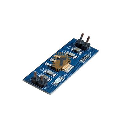
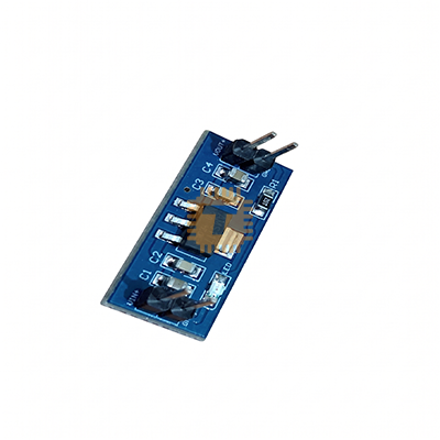
The AMS1117 9V To 5V DC-DC Step-Down Power Supply Module 800mA is an ultra-compact, high-stability voltage regulation breakout board engineered to deliver a clean, ripple-free 5.0V DC power rail for microcontrollers, sensor arrays, radio modules, and digital logic circuits. Powered by the popular AMS1117-5.0 positive low-dropout linear regulator IC in an SOT-223 surface-mount package, it steps down unstable or higher-level DC sources (such as 9V batteries, 12V wall adapters, or unregulated battery banks) with tight ±1.5% voltage precision. Equipped with dual-row 2.54mm (0.1") gold-plated header pins, onboard input/output noise-filtering capacitors, and a red SMD power status LED, it is a staple power conditioning module for breadboard prototyping, custom carrier boards, and embedded systems.
Specifications
- Regulator IC: AMS1117-5.0 (Positive Low Dropout / LDO Linear Voltage Regulator)
- Input Voltage Range (VIN): 6.0 V to 12.0 V DC (Nominal 9.0 V DC / Maximum Limit: 15.0 V DC)
- Regulated Output Voltage (VOUT): 5.0 V DC (±1.5?curacy / ±0.075 V Tolerance)
- Maximum Continuous Output Current (IOUT): Up to 800 mA to 1.0 A Max. (Subject to thermal dissipation limits)
- Recommended Continuous Load Current: 400 mA to 500 mA (For prolonged thermal reliability)
- Dropout Voltage (VDROP): Typ. 1.1 V to 1.3 V at IOUT = 800 mA
- Minimum Required Input Voltage: VOUT + VDROP ≈ 6.3 V DC (at full rated 800 mA load)
- Quiescent / Ground Current (IQ): Approx. 5 mA to 11 mA
- Line Regulation: ≤ 0.2% (VIN = 6.5 V to 12.0 V, IOUT = 10 mA)
- Load Regulation: ≤ 0.4% (IOUT = 10 mA to 800 mA)
- Ripple Rejection Ratio (PSRR): > 60 dB to 75 dB (at f = 120 Hz)
- Onboard Filtering Capacitors: Dual Surface-Mount Ceramic / Tantalum Capacitors (Input: 10 μF, Output: 10 μF / 22 μF for transient suppression)
- Status Indication: Onboard Red SMD Power Indicator LED (Tied across VOUT with series resistor)
- Interface Pinout: Standard Dual-Row 2-Pin / 4-Pin 2.54 mm (0.1 Inch) Pitch Header Pins
- Thermal & Overcurrent Protection: Built-in Thermal Overload Protection (Junction Cutoff at TJ ≈ 150°C) and Internal Current Limiting (Short-Circuit Safe)
- Operating Temperature Range: -40°C to +125°C
- PCB Dimensions: Approx. 26 mm × 12 mm × 10 mm (L × W × H including male header pins)
- Net Weight: Approx. 2.0 g to 3.5 g
Pinout & Terminal Definition
- Input Interface (VIN / VCC): Positive Unregulated DC Input Rail (Connects to +6.0 V to +12.0 V DC, e.g., 9V Battery Positive terminal)
- Output Interface (VOUT / 5V): Regulated Positive 5.0 V DC Output Rail (Supplies logic circuits, sensors, and 5V microcontrollers)
- Ground Interface (GND): Common Negative Reference Ground (0 V) / Return path for both Input and Output circuits
Features
- Clean, Ripple-Free Linear Regulation: Operates without high-frequency switching noise, inductor whine, or EMI, making it ideal for powering noise-sensitive analog-to-digital converters (ADCs), audio preamplifiers, and precision analog sensors.
- Integrated Filtering Network: Onboard input and output bypass capacitors stabilize the internal feedback amplifier, eliminate parasitic self-oscillation, and smooth out line transients.
- Standard Breadboard Pitch (2.54mm): Pre-soldered single or dual-row header pins plug directly into solderless breadboards, perfboards, and female Dupont jumper cables.
- Comprehensive Built-In Silicon Safeguards: Integrates internal thermal shutdown circuitry and foldback short-circuit current limiting to prevent catastrophic semiconductor burnout under sustained faults.
- Convenient Visual Power Confirmation: Features an onboard red SMD LED that illuminates immediately upon successful regulation, providing quick diagnostic status.
Common Applications
- Microcontroller Core Power: Providing regulated 5V DC to Arduino Nano/Pro Mini, ATmega328P chips, PIC microcontrollers, and 8051 systems from 9V PP3 batteries or 12V adapters.
- Sensor Power Distribution: Clean power rail for 5V analog and digital modules (e.g., MQ gas sensors, ultrasonic rangefinders, Hall effect sensors, and analog strain gauges).
- Relay & Display Modules: Powering 5V electromechanical relay boards, I2C 1602 LCDs, and OLED displays from higher chassis supply rails.
- Audio & RF Receiver Front-Ends: Supplying low-noise DC power to FM receivers, wireless RF 433MHz decoders, and discrete audio op-amps (e.g., NE5532, LM358).
- Educational Prototyping: Compact plug-in power source for student STEM kits, breadboard experiments, and DIY robotics sensor shields.
Usage Tips
- Thermal Dissipation Calculation (CRITICAL):
- As a linear regulator, the AMS1117 dissipates the voltage difference between input and output as pure waste heat: PD = (VIN - VOUT) × IOUT.
- When stepping down from 9V to 5V (VIN = 9.0 V, VOUT = 5.0 V): Voltage drop is 4.0 V. If drawing 400 mA (0.4 A), power dissipated as heat is PD = 4.0 V × 0.4 A = 1.6 W.
- Because the SOT-223 package on this small PCB can safely dissipate approximately 0.8 W to 1.0 W without an external heatsink, keep continuous load currents below 200 mA to 250 mA when powering from a 9V or 12V source to avoid triggering thermal shutdown.
- For high-current continuous loads (>500 mA from 9V/12V), consider adding a small clip-on copper/aluminum heatsink to the tab or switching to an inductive buck regulator (e.g., LM2596 or MP1584).
- Polarity Verification: The module does not feature a series reverse-polarity blocking diode. Verify that the positive supply line connects to VIN and the negative line connects to GNDbefore powering on; reversed input polarity will permanently destroy the AMS1117 IC.
- Dropout Voltage Headroom: Always maintain at least 1.3V difference between input and output (VIN ≥ 6.3V). If an aging 9V alkaline battery drops below ~6.2V, the output voltage will fall below 5.0V, potentially causing microcontroller brownout resets.
- Output Short-Circuit Caution: While the IC features internal thermal and current limiting, sustained direct output short circuits at high input voltages (VIN > 9V) will cause severe localized junction overheating and may damage the IC package over time.
- RF & Analog Isolation: For high-sensitivity analog circuitry (e.g., 24-bit ADCs or microphone preamps), place an additional 0.1 μF ceramic capacitor in parallel with a 100 μF low-ESR electrolytic capacitor directly across the output pins to eliminate residual low-frequency ripple.
Sharing is caring, show love and share the product with your friends.
Featured


Add to Cart

Add to Cart
Other Products

Add to Cart
Add to Cart

Add to Cart
