
ESP8266 ATmega2560 MEGA Dev Board R3 32Mb WiFi Bluetooth IoT (MD0205) Products

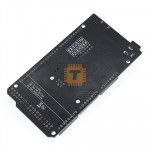
| Name | ESP8266 ATmega2560 MEGA Dev Board R3 32Mb WiFi Bluetooth IoT |
| Code | MD0205 |
| Price | Rs.4,600.00 |
| In Stock | Yes |
| Package | MODULE |
Product Details
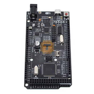
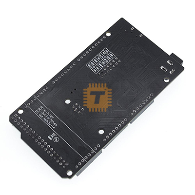
The MEGA + WiFi R3 is a powerful, integrated development board that combines the massive I/O capabilities of the ATmega2560 with the wireless connectivity of the ESP8266 on a single PCB. It is an ideal "all-in-one" solution for complex IoT projects that require high pin counts and robust WiFi performance without the clutter of external modules and jumper wires.
Specifications
- Microcontrollers: ATmega2560 (8-bit) and ESP8266 (32-bit).
- WiFi Flash Memory: 32Mb (4MB).
- USB-to-Serial: CH340G (Requires CH340 driver installation).
- Operating Voltage: 5V (USB) or 7V–12V via DC Jack.
- Digital I/O Pins: 54 (15 provide PWM output).
- Analog Input Pins: 16.
- ESP8266 Antenna: Onboard PCB antenna with a socket for an external IPX antenna.
DIP Switch Configuration
The board features a central 8-position DIP switch that controls how the USB, ATmega2560, and ESP8266 communicate with each other.
| Connection Mode | 1 | 2 | 3 | 4 | 5 | 6 | 7 |
| USB <-> ATmega2560 (Standard Mega) | OFF | OFF | ON | ON | OFF | OFF | OFF |
| USB <-> ESP8266 (Firmware/Sketch) | OFF | OFF | OFF | OFF | ON | ON | ON |
| USB <-> ESP8266 (Comm. Only) | OFF | OFF | OFF | OFF | ON | ON | OFF |
| ATmega2560 <-> ESP8266 | ON | ON | OFF | OFF | OFF | OFF | OFF |
| All Independent | OFF | OFF | OFF | OFF | OFF | OFF | OFF |
Special Solution Mode
USB <-> ATmega2560 <-> ESP8266
To connect the USB to both the ATmega2560 and ESP8266 simultaneously (routing through Serial3/RXD3/TXD3):
- DIP Switches 1–4: ON
- DIP Switches 5–7: OFF
- SWITCH 2: To RXD3/TXD3
Features
- Integrated Design: Both modules share the same power supply and serial bus via the DIP switches, reducing space and power consumption.
- Massive I/O: Retains the full 54 digital and 16 analog pins of the Mega R3, making it capable of handling large sensor arrays and multiple actuators.
- Flexible Programming: You can upload sketches to either the Mega or the ESP8266 individually by adjusting the toggle switches.
- Toggle Switch (Mode Select): Includes a small toggle switch near the ESP8266 to switch between "Work" mode and "Upgrade" (Firmware) mode.
Common Applications
- Smart Home Hubs: Using the Mega to control relays and lights while the ESP8266 hosts a web dashboard.
- Industrial Monitoring: Reading dozens of industrial sensors and uploading the data to a cloud database.
- Robotics: Managing complex motor movements while receiving remote commands over WiFi.
- Data Loggers: Storing local data and syncing with an NTP server for precise time-stamping.
Usage Tips
- Driver Setup: Ensure you install the CH340 driver on your computer before attempting to upload sketches.
- Power Stability: When running both chips simultaneously, use the DC power jack (9V–12V) rather than USB alone to ensure stable current for the WiFi module's peaks.
- Switching Modes: Always power off the board or disconnect USB before flipping the DIP switches to prevent serial communication errors or short circuits.
- Serial Communication: When the Mega and ESP8266 are linked (DIP 1 & 2 ON), they communicate via Serial3 on the Mega.
Sharing is caring, show love and share the product with your friends.
Featured

Add to Cart

Add to Cart

Add to Cart
Other Products
Add to Cart

Add to Cart

Add to Cart
