
FNIRSI LPM-10A Networking Cable Tester Smart Locator Line Tracker RJ45 RJ11 (TA1967) Products
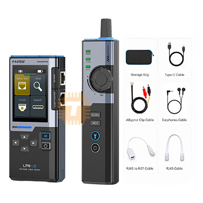
| Name | FNIRSI LPM-10A Networking Cable Tester Smart Locator Line Tracker RJ45 RJ11 |
| Code | TA1967 |
| Price | Rs.19,250.00 |
| In Stock | Yes |
| Package | METER |
Product Details
The FNIRSI LPM-10A Networking Cable Tester Smart Locator Line Tracker RJ45 RJ11 is a multifunctional digital network wire tracker and cable diagnostic instrument designed for telecommunications technicians, IT network administrators, and structured cabling installers. Comprising an intelligent digital signal transmitter (emitter) and a high-sensitivity anti-interference receiver probe, it performs non-destructive line tracing, pin-to-pin wire mapping, open/short/cross fault detection, PoE (Power over Ethernet) voltage presence verification, and port flashing diagnostics across RJ45 (Cat5e/Cat6/Cat6a/Cat7), RJ11/RJ12 telephony cables, and bare metal conductor pairs. Featuring advanced digital audio signal encoding, it filters out 50Hz/60Hz AC mains hum and high-frequency network switch noise, enabling pinpoint cable identification across congested patch panels, server racks, conduits, and drywall bundles.
Specifications
- Instrument Model / Series: FNIRSI LPM-10A Smart Network Cable Tester & Wire Tracker
- System Configuration: Dual-Unit Set (Transmitter / Emitter Unit + Receiver / Sensor Probe Unit)
- Compatible Cable Types: RJ45 (Cat5, Cat5e, Cat6, Cat6a, Cat7 UTP/STP), RJ11/RJ12 Telephone Lines, BNC Coaxial (via adapter), and General 2-Core Metal Wires (via Alligator Clips)
- Tracking / Tracing Technology: Advanced Digital Encoded Signal + Analog Dual-Mode Tone Generator (Anti-interference filter)
- Maximum Wire Tracing Distance: Up to 300 meters (Approx. 1,000 feet)
- Signal Output Frequency: ~455 kHz (Digital tone modulation)
- Wire Mapping Function (Pin-to-Pin Test):
- Detects: Straight-through, Open circuits, Short circuits, Cross-wiring, Split pairs, and Shield continuity (G)
- Indicator Display: 8 Individual LED indicators (Pins 1–8) + 1 Shield Ground LED (G) on both transmitter and receiver
- Port Flashing / Hub Blink Function: Generates low-frequency link pulses to flash switch/router port status LEDs at a distinctive ~1Hz to 2Hz rate
- PoE (Power over Ethernet) Testing:
- Detection Capability: Identifies PoE voltage presence and power polarity (Endspan 1/2, 3/6 or Midspan 4/5, 7/8)
- Input Voltage Detection Range: DC 5 V to 60 V
- Standard Compliance: IEEE 802.3af / IEEE 802.3at detection
- Telephone Line Status Test (RJ11 Mode): Detects Line Polarity (Positive/Negative), Ringing signal presence, and Line State (Idle / Off-Hook / Ringing)
- Maximum Withstand / Live Voltage Protection: Up to 60 V DC live circuit withstand capability on transmitter RJ45/RJ11 ports
- Audio Output: Built-in speaker on receiver with adjustable volume rotary thumbwheel + 3.5mm Headphone Jack (for noisy server rooms)
- Auxiliary Illumination: High-brightness white LED work light integrated into the receiver probe tip
- Power Supply:
- Transmitter: 1 × 9V 6F22 Alkaline / Heavy Duty Battery (or internal rechargeable lithium cell depending on sub-revision)
- Receiver: 1 × 9V 6F22 Alkaline / Heavy Duty Battery
- Battery Life: ≥ 8 to 12 hours continuous operation; Auto power-off after ~15 to 20 minutes idle
- Operating Environmental Limits: 0°C to +40°C; 20% to 80% RH non-condensing
- Dimensions:
- Transmitter: Approx. 130 × 65 × 30 mm
- Receiver: Approx. 200 × 40 × 30 mm
- Net Weight: Approx. 250 g to 300 g (combined set without batteries)
Features
- Digital Anti-Noise Filtering: Uses digital pulse modulation to filter out acoustic buzzing and hum generated by nearby 230V/110V AC mains lines, fluorescent ballasts, and variable-frequency drives (VFDs), ensuring clear cable tone detection.
- Live Network & PoE Voltage Tolerant: Transmitter withstands connections to active live Ethernet ports with up to 60V DC PoE supply without burning out internal detection circuitry.
- Visual Port Flashing (Hub Blink): Locates target switch ports without disconnecting cables by pulsing the link LED on active managed/unmanaged switches at an identifiable, synchronized flash rate.
- Shield Continuity Verification: Dedicated 'G' LED indicator on both the emitter and receiver verifies the ground/drain wire integrity of STP, FTP, and SFTP shielded network lines.
- Dual-Tone Audio & Headphone Port: Includes a standard 3.5mm headphone jack on the receiver probe, allowing technicians to trace cables clearly in deafening data center environments without disturbing adjacent racks.
- Integrated Probe Tip Worklight: Front-facing white LED illuminates dark ceiling crawlspaces, wiring closets, and rear server cabinet channels.
Common Applications
- Structured Cabling Installation: Validating RJ45 pin assignments, identifying split pairs, and testing termination crimp quality in office and commercial network rollouts.
- Server Room & Data Center Tracing: Tracing individual patch cords through dense cable management raceways and patch panels back to individual server NIC ports.
- PoE Device Commissioning: Verifying PoE voltage presence and power pair assignments before connecting IP surveillance cameras, VoIP phones, and Wi-Fi access points.
- Telecommunications & PBX Maintenance: Checking analog phone line continuity, polarity, and ring voltage on RJ11/RJ12 distribution blocks (PABX systems).
- Wire Harness & Coaxial Inspection: Tracing multi-conductor automotive wiring harnesses, alarm sensor loops, and intercom cabling using the included alligator clip breakout lead.
Usage Tips
- Live Cable & Switch Tracing Procedure:
- When tracing a cable plugged into an active Ethernet switch, switch the LPM-10A transmitter to "Digital Scan" mode.
- Move the receiver probe along the bundle; adjust the receiver's rotary volume wheel down as you approach the patch panel to isolate the target jack from adjacent crosstalk bleed.
- Port Flashing (Hub Blink) Best Practice:
- If tracing through shielded metal patch bays yields ambiguous audio signals, plug the cable into the transmitter and select the "Port Flash" function.
- Walk over to the switch rack and observe the port LEDs: the port connected to the LPM-10A will flash in a distinct 1-second pulse pattern, identifying the physical port immediately.
- RJ45 Wire Mapping Sequence:
- Plug one end of the finished network cable into the transmitter's RJ45 socket and the opposite end into the receiver's RJ45 socket.
- Switch to "Wiremap" (Network Test) mode. Observe the sequential sweep of LEDs 1 through 8 (and G):
- Normal Straight-Through: LEDs illuminate 1-2-3-4-5-6-7-8 sequentially on both units.
- Cross / Mismatched: LEDs flash out of numerical sequence (e.g., 1-2-3-6 swapped on T568A vs. T568B).
- Open Circuit: The LED corresponding to the broken core remains unlit.
- Short Circuit: Multiple LEDs light up simultaneously on the receiver.
- Mains Voltage Precaution (CRITICAL):
- While the tester is protected against standard low-voltage PoE systems (up to 60V DC), NEVER connect the transmitter directly to live 110V/230V AC mains electricity.
- Doing so will instantly destroy the internal microcontroller and create an electric shock hazard. Always verify with a contactless voltage tester (NCV) that building power lines are de-energized before connecting alligator clips.
- Receiver Sensitivity Adjustment: When searching through dense, tightly bundled trunk cables, set the sensitivity wheel to maximum to detect the general bundle path, then turn the sensitivity down as you separate individual cables to isolate the exact target conductor.
Sharing is caring, show love and share the product with your friends.
Featured

Add to Cart

Add to Cart

Other Products


Add to Cart

Add to Cart
