LED Bar Graph Display Battery 4 Colour 10 Segment Red Yellow Green Blue (RRYYYGGGGB) QH-B10BBGYR (DM0036) Products
| Name | LED Bar Graph Display Battery 4 Colour 10 Segment Red Yellow Green Blue (RRYYYGGGGB) QH-B10BBGYR |
| Code | DM0036 |
| Price | Rs.140.00 |
| In Stock | Yes |
| Package | THT |
Product Details
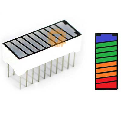
The QH-B10BBGYR is a 10-segment multi-colour LED bar graph display tailored specifically for battery level gauges, capacity indicators, and state-of-charge (SoC) meters. Arranged in a progressive reverse orientation—2 Red, 3 Yellow, 4 Green, and 1 Blue segment (R-R-Y-Y-Y-G-G-G-G-B)—it naturally maps empty-to-full capacity or critical-to-optimal status. Packaged in an industry-standard 20-pin dual in-line package (DIP-20) with a high-contrast black faceplate and diffused segment bars, it provides immediate, readable feedback across consumer, automotive, and industrial instrumentation panels.
Specifications
- Model: QH-B10BBGYR
- Display Type: 10-Segment LED Bar Graph
- Segment Colour Sequence: 2 Red, 3 Yellow, 4 Green, 1 Blue (R-R-Y-Y-Y-G-G-G-G-B)
- Package Style: 20-Pin Dual In-line Package (DIP-20)
- Pin Pitch: 2.54 mm (Standard breadboard and perfboard spacing)
- Row Spacing: 7.62 mm (0.3 inches standard DIP width)
- Forward Current per Segment: 15mA to 20mA (Nominal), 30mA (Peak absolute max)
- Forward Voltage Drops (Typical at 20mA):
- Red: 1.8V to 2.2V
- Yellow: 2.0V to 2.4V
- Green: 2.1V to 2.4V (or 3.0V to 3.2V for true-green variants)
- Blue: 3.0V to 3.3V
- Reverse Voltage Max: 5V
- Operating Temperature: -25°C to +85°C
- Surface / Segment Finish: Black faceplate with white diffused segment windows for optimal on/off contrast
Interface and Pinout Guide
Each segment is electrically isolated with independent anode and cathode connections routed to opposite sides of the DIP-20 package:
- Pin Rows: 2 parallel rows of 10 pins spaced 7.62 mm (0.3 inches) apart.
- Segment 1 (Red): Pin 1 to Pin 20
- Segment 2 (Red): Pin 2 to Pin 19
- Segment 3 (Yellow): Pin 3 to Pin 18
- Segment 4 (Yellow): Pin 4 to Pin 17
- Segment 5 (Yellow): Pin 5 to Pin 16
- Segment 6 (Green): Pin 6 to Pin 15
- Segment 7 (Green): Pin 7 to Pin 14
- Segment 8 (Green): Pin 8 to Pin 13
- Segment 9 (Green): Pin 9 to Pin 12
- Segment 10 (Blue): Pin 10 to Pin 11
(Note: Because all 10 diode segments are electrically isolated, the display can be wired in Common Anode, Common Cathode, or multiplexed matrix configurations directly through PCB trace routing or external breadboard jumpers).
Key Features
- Battery-Optimized Colour Progression: Starting with Red for critical low/reserve capacity, transitioning through Yellow for warning/moderate charge, Green for healthy operating range, and topping off with Blue for 100% full or charging status.
- Fully Isolated LED Channels: Independent pin pairs for every segment allow versatile driving via low-side sinking, high-side sourcing, shift registers, or specialized display drivers.
- High Contrast and Uniform Diffusion: Dark faceplate combined with diffused segment windows prevents optical bleed-through and ensures high readability in daylight or dimly lit environments.
- Standard DIP-20 Form Factor: Directly compatible with standard 2.54 mm pitch breadboards, prototyping perfboards, and 20-pin IC sockets.
- Broad Driver IC Compatibility: Directly interfaces with display drivers like the LM3914 (linear mode), LM3915 (logarithmic mode), 74HC595 shift registers, or standard microcontroller GPIO pins.
Common Applications
- Battery Management Systems (BMS): Visual capacity and state-of-charge (SoC) gauges for power banks, solar energy storage systems, and e-bikes.
- Charging Stations & Power Supplies: Live charge-cycle monitoring from empty (Red) up to floating/trickle charge complete (Blue).
- Industrial Fill & Pressure Gauges: Monitoring fluid levels, vessel depletion, or pneumatic pressures with intuitive bottom-up alerts.
- Embedded Development & Dashboards: Status readouts for robotics, portable instruments, and maker platforms based on Arduino, ESP32, and Raspberry Pi.
Usage Tips
- Current Limiting Resistors: Always connect individual current-limiting resistors to each segment. Because Red, Yellow, Green, and Blue diodes have different forward voltage drops, size resistors accordingly (or use 220Ω to 470Ω resistors per pin on a 5V supply) to ensure uniform visual brightness across all four colours.
- Polarity Confirmation: Check each segment with a digital multimeter in diode-test mode before final soldering to verify your intended anode and cathode orientation relative to Pin 1.
- Total Supply Load: When illuminating all 10 segments simultaneously at 15mA, total consumption reaches approximately 150mA. Ensure your driver IC or power rail can supply this current without dropping logic voltage levels.
Sharing is caring, show love and share the product with your friends.
Featured

Add to Cart

Add to Cart