MAX7219 8-Digit Digital LED Tube Display Module Red (MD0236) Products
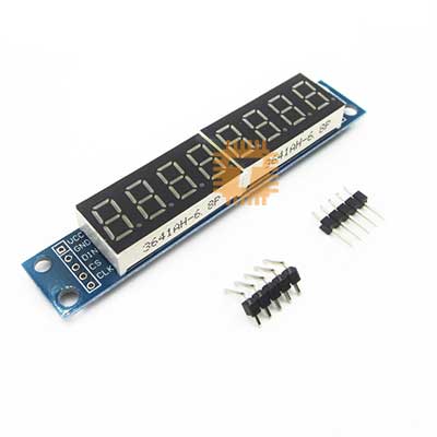
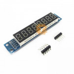
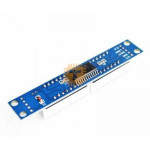
| Name | MAX7219 8-Digit Digital LED Tube Display Module Red |
| Code | MD0236 |
| Price | Rs.350.00 |
| In Stock | Yes |
| Package | MODULE |
Product Details
The MAX7219 8-Digit Digital LED Tube Display Module is an integrated serial input/output common-cathode display driver that connects microcontrollers to 8-digit 7-segment numeric LED displays. It uses a compact 3-wire SPI-compatible serial interface, allowing you to control all 8 digits using just three data pins from your microcontroller. This drastically reduces the GPIO overhead needed to run multi-digit displays in custom electronics.
Specifications
- Driver IC: MAX7219 Serially Interfaced, 8-Digit Display Driver
- Display Type: 8 Digits of Red Common-Cathode 7-Segment Displays (Arranged as two 4-digit blocks)
- Operating Voltage: 4.5V to 5.5V DC (5V recommended)
- Digital Interface: 3-Wire Serial SPI-compatible (CLK, CS, DIN)
- Maximum Clock Frequency: 10 MHz
- Cascading Ability: Features output breakout pins (DOUT, LOAD, CLK) to daisy-chain multiple modules together
Interface and Pinout Guide
Input Side (Connects to Microcontroller)
- VCC: 5V Power Input
- GND: Common Ground Reference
- DIN: Data Input Line (Connects to MCU MOSI or any Digital GPIO)
- CS / LOAD: Chip Select / Load Input Line (Connects to MCU Slave Select or Digital GPIO)
- CLK: Serial Clock Line (Connects to MCU Clock or Digital GPIO)
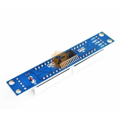
Output Side (Connects to Next Module for Cascading)
- VCC: 5V Power Pass-through
- GND: Ground Pass-through
- DOUT: Serial Data Output (Connects to the DIN of the next module)
- LOAD / CS: Chip Select Pass-through
- CLK: Serial Clock Pass-through
Key Features
- Efficient Pin Savings: Direct drive of an 8-digit 7-segment display normally requires dozens of complex multiplexing tracks and GPIO pins. The MAX7219 slashes this requirement down to just 3 digital control lines.
- Hardware Multiplexing: The chip handles all the rapid scanning and refreshing of the LED digits internally, freeing up your main microcontroller's processor to handle more critical tasks.
- Onboard Current Limiting: Uses a single internal resistor to set the segment current for all LEDs, preventing brightness variations and safeguarding the display segments from over-current damage.
- Brightness Control: Supports digital brightness configuration via software using Pulse Width Modulation (PWM) internal registers, allowing you to change the intensity across 16 distinct levels.
Common Applications
- Digital Clocks and Timers: Displaying hours, minutes, seconds, or countdown intervals in custom timekeeping systems.
- Counter Systems: Serving as scoreboards, queuing line displays, or industrial tally monitors.
- Measurement Instruments: Outputting live readouts for digital voltmeters, frequency counters, and laboratory sensors.
- CNC and 3D Printers: Displaying real-time temperatures, coordinate steps, or print job percentages.
Usage Tips
- Voltage Drop Handling: The MAX7219 requires a stable 5V supply to display uniform brightness. Running it on 3.3V logic systems (like an ESP32 or Raspberry Pi) is safe for the control lines, but the VCC pin must still be connected to a dedicated 5V power rail.
- Daisy-Chaining Configuration: When cascading multiple displays, connect the output header (VCC, GND, DOUT, LOAD, CLK) of the first module directly to the input header of the next module. All units share the same CLK and CS lines, while data strings pass sequentially through the DOUT lines.
- Decoupling Capacitors: If you notice unexpected flickering or ghosting digits, place a 10 micro-Farad electrolytic capacitor and a 0.1 micro-Farad ceramic capacitor across the main VCC and GND pins right at the module input to filter out high-frequency switching noise.
Sharing is caring, show love and share the product with your friends.
Featured

Add to Cart

Add to Cart

Add to Cart
Other Products

Add to Cart