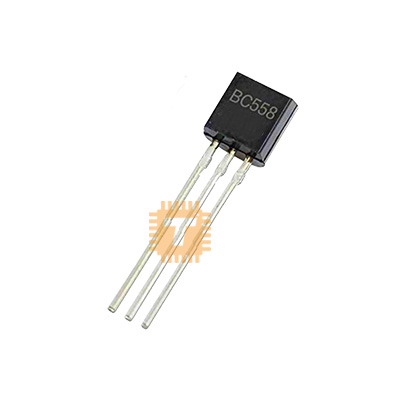
Original BC558 PNP Transistor TO-92 (DI0307) Products
| Name | Original BC558 PNP Transistor TO-92 |
| Code | DI0307 |
| Price | Rs.30.00 |
| In Stock | Yes |
| Package | TO-92 |
Product Details
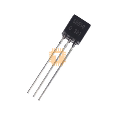
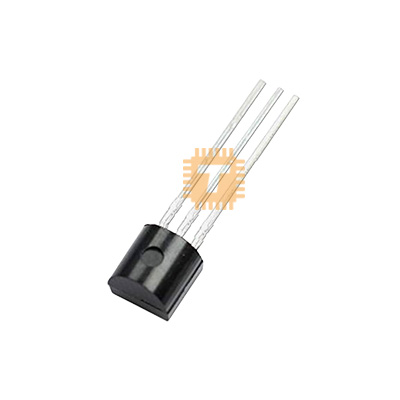
The Original BC558 PNP Transistor is a standard general-purpose silicon Epitaxial Planar Bipolar Junction Transistor (BJT) housed in a compact TO-92 (TO-226AA) through-hole plastic package. Engineered for low-noise audio pre-amplification, small-signal processing, and low-power general switching applications, the BC558 features a complementary polarity to the ubiquitous BC548 NPN transistor. It delivers a maximum collector-emitter breakdown voltage of 30V, continuous collector current of 100mA (with 200mA peak capability), low noise figure (typically 2 dB to 10 dB max), and high DC current gain across its sorted gain groups (A, B, and C). It is widely utilized in audio amplifier driver stages, signal inverter gates, sensor interface circuits, and general switching logic.
Specifications
- Part Number / Model: BC558 (Available in gain bins BC558A, BC558B, BC558C)
- Transistor Polarity / Type: PNP Silicon Bipolar Junction Transistor (BJT)
- Package Type: TO-92
- Collector-Emitter Voltage (Vceo): -30V (Max)
- Collector-Base Voltage (Vcbo): -30V (Max)
- Emitter-Base Voltage (Vebo): -5.0V (Max)
- Continuous Collector Current (Ic): -100mA (Max)
- Peak Collector Current (Icm): -200mA (Max)
- Peak Base Current (Ibm): -200mA (Max)
- Total Device Dissipation (Ptot): 500mW (at Ta = 25°C) / 625mW (standard TO-92 derating)
- DC Current Gain (hFE): 110 to 800 (BC558A: 110–220, BC558B: 200–450, BC558C: 420–800 at Vce = -5V, Ic = -2mA)
- Collector-Emitter Saturation Voltage (Vce(sat)): Typ. -90mV / Max. -300mV (at Ic = -10mA, Ib = -0.5mA); Max. -650mV (at Ic = -100mA, Ib = -5.0mA)
- Base-Emitter Saturation Voltage (Vbe(sat)): Typ. -700mV (at Ic = -10mA, Ib = -0.5mA)
- Transition Frequency / Gain-Bandwidth Product (fT): Typ. 100 MHz to 250 MHz (at Vce = -5V, Ic = -10mA, f = 100MHz)
- Collector Capacitance (Cc): Typ. 2.5pF / Max. 4.5pF (at Vcb = -10V, f = 1MHz)
- Noise Figure (NF): Typ. 2.0 dB / Max. 10 dB (at Vce = -5V, Ic = -0.2mA, Rs = 2kΩ, f = 1kHz, B = 200Hz)
- Operating Junction Temperature (Tj): -65°C to +150°C
- Storage Temperature Range (Tstg): -65°C to +150°C
- Thermal Resistance, Junction to Ambient (Rth(j-a)): 200°C/W to 250°C/W
- Pinout Configuration: Pin 1: Collector (C), Pin 2: Base (B), Pin 3: Emitter (E) [Standard European TO-92 layout with flat face toward viewer]
Features
- Complementary PNP Architecture: Perfect complementary pair to the standard BC548 NPN transistor for push-pull output stages and balanced differential pairs.
- Low Noise Figure: Optimized low internal noise characteristics make it well-suited for high-fidelity audio pre-amplifiers and microphone input stages.
- Low Saturation Voltage: Low Vce(sat) ensures minimal power drop and cool operation during low-current saturation switching states.
- Versatile High-Gain Grading: High hFE options (up to 800 in the C-group) permit high amplification linearity even at low base drive currents.
- Standard TO-92 Packaging: Robust, industry-standard plastic mold allows seamless integration into breadboards, prototyping stripboards, and automated PCB assembly lines.
Common Applications
- Audio Preamplifier Stages: Low-noise signal conditioning, microphone preamps, and headphone driver circuits.
- Push-Pull & Class-AB Amplifiers: Complementary symmetry output driver stages paired with BC547/BC548 NPN transistors.
- Small-Signal Switching: Low-side/high-side signal inversion, indicator LED switching, and small relay coil drivers (up to 100mA).
- Sensor Interface & Conditioning: Analog front-end amplification for light, temperature, and acoustic sensor circuits.
- Current Mirrors & Constant Current Sources: Precision current balancing and active load biasing in analog circuits.
Usage Tips
- High-Side Switching Configuration: As a PNP transistor, connect the Emitter to the positive supply rail (+Vcc) and the Collector to the high side of the load; apply a LOW logic level (0V/GND) to the Base via a current-limiting resistor to turn the load ON.
- Base Resistor Sizing: Always calculate the base resistor (Rb) based on saturation current requirements: Rb = (Vsource - Vbe) / Ib. For full saturation, use a forced gain (hFE forced) ratio of 10 to 20 (Ib = Ic / 10).
- European Pinout Caution: Pay close attention to the standard European TO-92 pin configuration (Pin 1: Collector, Pin 2: Base, Pin 3: Emitter from left to right, flat face facing you); do not confuse it with American 2N-series transistors (which typically use E-B-C pinout).
- Flyback Diode on Inductive Loads: When switching inductive components like miniature relay coils or buzzers, always place a reverse-biased diode (e.g., 1N4148 or 1N4007) across the load to protect the transistor from high-voltage turn-off inductive spikes.
Sharing is caring, show love and share the product with your friends.
Featured

Add to Cart


Add to Cart

Add to Cart