Original D13009K NPN Power Transistor TO-247 (DI0281) Products
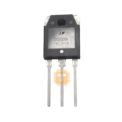
| Name | Original D13009K NPN Power Transistor TO-247 |
| Code | DI0281 |
| Price | Rs.350.00 |
| In Stock | Yes |
| Package | THT |
Product Details
The D13009K (commonly marked as 3DD13009K / KSE13009L) is a high-voltage, high-speed NPN silicon power bipolar junction transistor housed in a heavy-duty TO-247 (TO-3P) through-hole package. Specifically engineered for high-frequency switch-mode power conversion, the D13009K features a high collector-emitter breakdown voltage of 400V (with VCBO up to 700V), a continuous collector current rating of 12A, low saturation voltage, and fast switching fall times. It is widely used in high-power ATX switch-mode power supplies (SMPS), electronic ballasts, fluorescent lighting inverters, and high-voltage motor drives.
Specifications
- Brand / Manufacturer: Fairchild / ON Semiconductor / JILIN SINO-MICROELECTRONICS / Industry Standard
- Part Number / Marking: D13009K / 3DD13009K / KSE13009
- Transistor Type: High-Voltage Fast-Switching NPN Power BJT
- Collector-Base Voltage (VCBO): 700V
- Collector-Emitter Voltage (VCEO): 400V
- Emitter-Base Voltage (VEBO): 9.0V
- Continuous Collector Current (IC): 12A
- Pulsed Collector Current (ICM): 24A
- Continuous Base Current (IB): 6.0A
- DC Current Gain (hFE): 8 to 40 (at IC = 5.0A, VCE = 5.0V) / 6 to 30 (at IC = 8.0A, VCE = 5.0V)
- Collector-Emitter Saturation Voltage (VCE(sat)): < 1>C = 5.0A, IB = 1.0A) / < 1>C = 8.0A, IB = 1.6A)
- Base-Emitter Saturation Voltage (VBE(sat)): < 1>C = 5.0A, IB = 1.0A)
- Transition Frequency (fT): Approx. 4.0 MHz (Minimum at IC = 0.5A, VCE = 10V)
- Fall Time (tf): Approx. 0.2µs to 0.7µs (Fast inductive load turn-off)
- Total Power Dissipation (PD): Up to 100W to 130W (at TC = 25°C with heatsink)
- Operating Junction & Storage Temperature: -65°C to +150°C
- Package / Case: TO-247 / TO-3P (3-Pin Through-Hole: Pin 1: Base, Pin 2: Collector, Pin 3: Emitter, Mounting Tab: Collector)
Features
- High Reverse Voltage Withstand: 700V collector-base blocking voltage makes it resilient against high-voltage inductive spikes and offline AC line transients.
- High Current Handling: Delivers continuous current capability up to 12A (24A pulsed) for high-wattage primary power stages.
- Fast Switching Speeds: Low storage and fall times optimize efficiency and minimize switching losses in high-frequency SMPS topologies up to 100kHz.
- Heavy-Duty TO-247 Package: Large thermal mounting tab provides superior heat transfer and thermal stability compared to TO-220 packages under continuous heavy loads.
- Optimized Switching Linearity: Engineered with planar diffusion technology to ensure stable reverse bias safe operating area (RBSOA).
Common Applications
- Switch-Mode Power Supplies (SMPS): Primary half-bridge and push-pull switching transistors in high-wattage ATX computer power supplies and industrial DC power units.
- Electronic Ballasts & Lighting: High-frequency resonant inverters for compact fluorescent lamps (CFL) and HID lighting circuits.
- High-Voltage Inverters & Converters: DC-to-AC power conversion and high-voltage step-down/step-up converter topologies.
- Industrial Motor Drives: High-voltage PWM switching and speed control for AC/DC motors and inductive actuators.
- Uninterruptible Power Supplies (UPS): Offline inverter switching stages for battery-backup power systems.
Usage Tips
- Heatsink Mounting: Always mount the TO-247 tab securely to an aluminum heatsink using thermal grease; use an insulating mica/silicone pad and bushing if the heatsink must remain electrically isolated (Tab is internally connected to Collector).
- Base Drive Optimization: Provide an adequate base drive current (IB ≈ IC / 5 to IC / 8) to ensure deep saturation; using a proportional base-drive transformer or negative turn-off bias will significantly reduce storage time and switching losses.
- Snubber Circuit Protection: When driving inductive transformers or coils, always incorporate a primary RCD snubber network across the collector to clamp transient inductive spikes below the 700V rating.
- Base-to-Emitter Resistor: Connect a low-value resistor (e.g., 22Ω to 100Ω) or reverse anti-parallel diode across the Base and Emitter to speed up carrier evacuation during turn-off and prevent false triggering.
Sharing is caring, show love and share the product with your friends.
Featured

Add to Cart