Original IRF520N Power MOSFET THT (DI0318) Products
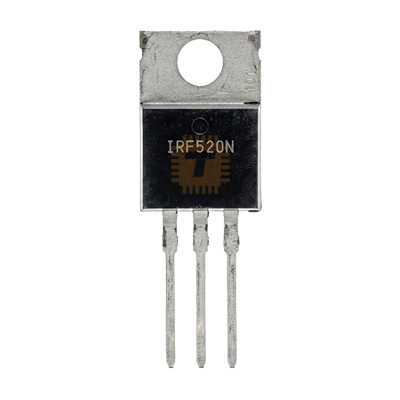
| Name | Original IRF520N Power MOSFET THT |
| Code | DI0318 |
| Price | Rs.160.00 |
| In Stock | Yes |
| Package | THT |
Product Details
The Original IRF520N N-Channel Advanced HEXFET Power MOSFET (100V / 9.7A / TO-220AB) is a widely utilized, rugged power MOSFET engineered for fast switching, low on-state resistance, and cost-effective power conversion applications. Utilizing planar stripe and advanced HEXFET process technology, it delivers low on-resistance (RDS(on) max. 0.200Ω), high dynamic dV/dt ruggedness, and fully characterized avalanche voltage and current ratings. Encapsulated in an industry-standard through-hole TO-220AB package, it provides continuous drain current handling up to 9.7A at 100V breakdown rating. The IRF520N is commonly used in DC-DC converters, motor speed control, solenoid and relay actuators, high-speed power switching, and microcontroller-interfaced DC load switching stages.
Specifications
- Part Number / Model: IRF520N / IRF520NPbF
- Transistor Polarity: N-Channel Enhancement Mode Power MOSFET
- Package Type: TO-220AB (Through-Hole 3-Lead Power Package with Metal Mounting Tab)
- Drain-Source Breakdown Voltage (VDSS): 100 V (Min. at VGS = 0V, ID = 250µA)
- Gate-Source Voltage (VGS): ±20 V Max.
- Continuous Drain Current (ID):
- At TC = 25°C: 9.7 A (at VGS = 10V)
- At TC = 100°C: 6.8 A
- Pulsed Drain Current (IDM): Up to 38 A (Pulse width limited by max Tj)
- Static Drain-Source On-State Resistance (RDS(on)): Max. 0.200 Ω / 200 mΩ (at VGS = 10V, ID = 5.8A)
- Gate Threshold Voltage (VGS(th)): 2.0 V to 4.0 V (at VDS = VGS, ID = 250µA)
- Total Power Dissipation (PD): Up to 48 W (at TC = 25°C)
- Linear Derating Factor: 0.32 W/°C (Above 25°C)
- Single-Pulse Avalanche Energy (EAS): Approx. 91 mJ (at IAS = 5.8A, L = 5.4mH)
- Avalanche Current (IAR): 5.8 A
- Repetitive Avalanche Energy (EAR): 4.8 mJ
- Peak Diode Recovery dV/dt: 5.0 V/ns
- Total Gate Charge (Qg): Typ. 16 nC / Max. 24 nC (at VDS = 80V, VGS = 10V, ID = 5.8A)
- Gate-to-Source Charge (Qgs): 3.0 nC
- Gate-to-Drain ("Miller") Charge (Qgd): 6.8 nC
- Input Capacitance (Ciss): Typ. 330 pF (at VDS = 25V, VGS = 0V, f = 1.0MHz)
- Output Capacitance (Coss): Typ. 90 pF
- Reverse Transfer Capacitance (Crss): Typ. 20 pF
- Switching Times (at VDD = 50V, ID = 5.8A, RG = 24Ω, VGS = 10V):
- Turn-On Delay Time (td(on)): Typ. 4.5 ns
- Rise Time (tr): Typ. 20 ns
- Turn-Off Delay Time (td(off)): Typ. 16 ns
- Fall Time (tf): Typ. 8.1 ns
- Body Diode Continuous Forward Current (IS): Up to 9.7 A
- Body Diode Pulsed Current (ISM): Up to 38 A
- Body Diode Forward Voltage (VSD): Max. 1.3 V (at IS = 5.8A, VGS = 0V)
- Body Diode Reverse Recovery Time (trr): Typ. 80 ns (Max. 120 ns at IF = 5.8A, dI/dt = 100A/µs)
- Thermal Resistance (Junction-to-Case, RθJC): 3.1 °C/W
- Thermal Resistance (Case-to-Sink, Flat Greased Surface, RθCS): 0.50 °C/W Typ.
- Thermal Resistance (Junction-to-Ambient, RθJA): 62 °C/W
- Operating Junction & Storage Temperature (Tj, Tstg): -55°C to +175°C
- Pinout Configuration (TO-220 - Front View, Pins Facing Down):
- Pin 1: Gate (G) - Control Terminal
- Pin 2: Drain (D) - Connected internally to Metal Mounting Tab
- Pin 3: Source (S) - Power Return Terminal
- Mounting Tab: Drain (D)
Features
- Advanced HEXFET Technology: Delivers fast switching speeds, high dynamic dV/dt ruggedness, and low on-resistance for maximum power transfer efficiency.
- 175°C Operating Temperature Rating: Provides enhanced thermal operating margin and long-term reliability under elevated ambient and enclosure temperatures.
- Fully Avalanche Rated: 100% tested for single-pulse avalanche energy handling (EAS = 91 mJ) to withstand inductive transient kickbacks.
- Low Gate Charge (Qg = 16 nC): Enables rapid gate switching with low driving power requirements, minimizing high-frequency switching losses.
- Industry-Standard TO-220 Package: Through-hole mounting allows stand-alone PCB placement for low-power loads or easy screw-mounting to external aluminum heatsinks.
Common Applications
- DC Motor PWM Speed Control: Low-side switching and H-bridge configurations for small-to-medium brushed DC motors and actuators.
- Solenoid & Relay Drivers: High-speed solid-state switching for automotive relays, electronic locks, and pneumatic solenoid valves.
- Switch-Mode Power Supplies (SMPS) & DC-DC Converters: Primary switching stages in buck, boost, and flyback converter topologies.
- LED Dimming & Lighting Drivers: High-frequency PWM dimming for 12V, 24V, and 36V high-brightness LED arrays and strips.
- Microcontroller DC Load Switching: Interfacing microcontroller logic outputs (via intermediate driver stages) to high-current DC loads.
Usage Tips
- Gate Drive Voltage Requirement: The IRF520N is a standard-gate MOSFET (not a logic-level device). To achieve its specified low on-resistance (0.200Ω) and handle currents above 2A–3A, drive the gate with VGS = 10V to 12V. Driving directly with 3.3V or 5V logic signals will leave the MOSFET in its linear region, causing high internal resistance and rapid overheating under moderate loads. Use a small NPN transistor, optocoupler, or dedicated gate driver IC (e.g., TC4427, TC4420) to shift logic signals to 10V–12V.
- Pull-Down Resistor: Always connect a 10kΩ resistor between the Gate (Pin 1) and Source (Pin 3) to keep the gate pulled to Ground and prevent floating-gate false triggering during microcontroller boot-up.
- Series Gate Resistor: Insert a small series resistor (typically 10Ω to 100Ω) directly in line with the Gate pin to damp high-frequency gate ringing caused by PCB trace inductance and input capacitance.
- Heatsinking: In free air without a heatsink, power dissipation should not exceed 1.5W to 2W (equivalent to approx. 2A–3A continuous current). For loads exceeding 3A continuous, mount the TO-220 tab to an aluminum heatsink with thermal paste.
- Tab Isolation: The metal mounting tab is internally connected to Pin 2 (Drain). If multiple MOSFETs or transistors share a single common grounded heatsink, use mica or silicone insulating pads (Sil-Pads) along with an insulating shoulder bushing on the mounting screw.
- Flyback Protection for Inductive Loads: When switching inductive loads (motors, relays, coils), always connect a fast freewheeling diode (such as a 1N4007 or 1N5819 Schottky) in reverse-parallel across the load to clamp reverse inductive voltage spikes below 100V.
Sharing is caring, show love and share the product with your friends.
Featured

Add to Cart


Add to Cart

Other Products

Add to Cart