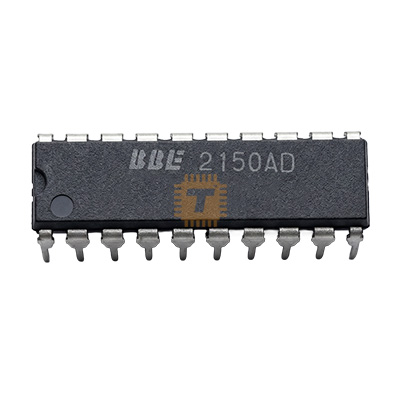
Original JRC2150AD Switching Controller IC DIP-16 (IC0344) Products
Name
Original JRC2150AD Switching Controller IC DIP-16
Code
IC0344
Price
Rs.590.00
In Stock
Yes
Package
THT
Product Details
The JRC2150AD (officially part of the NJM2150 series) is a hardwired, high-fidelity sound processor designed to replicate clear, real-life acoustic textures from a standard audio path. Operating as a specialized hardware "exciter/enhancer," the chip adjusts for phase shifts and transient losses inherent in typical loudspeakers. It features an internal BBE ON/OFF switch alongside dual-stage boost selectors for the high and low frequency bands, allowing immediate modification of the depth of the audio output field.
Specification
Product Series: NJM2150 / JRC2150
Package Form Factor: DIP-16 (Dual In-line Package, Through-Hole Mount)
Operating Supply Voltage (V⁺): 4.5V to 13.0V Direct Current (Typical: 9.0V)
Low Current Drain (Icc): Approx 8.0mA typical
Output Noise Profile: Superb low noise (approx 10 μVrms typical when BBE loop is active)
Bypass Gain: 0 dB unity gain
Dual-Stage Low Band Contour Boost: +2.5 dB or +5.5 dB (sampled at 20 Hz)
Dual-Stage High Band Definition Boost: +4.5 dB or +7.5 dB (sampled at 20 kHz)
Semiconductor Architecture: Bipolar Monolithic Linear Circuit
Features
Authentic BBE Phase Correction & Dynamic Boost: By modifying phase relationships across high, middle, and low frequency spectrum bands, it prevents high frequencies from reaching ears slightly delayed, eliminating muddy multi-speaker distortion.
Two-Grade Independent Contour Controls: Allows user control over both low-end bass thickness (Contour) and high-end crispness (Definition) via simple logical pull-high/pull-low step changes.
Integrated Electronic Mode Switching: No external relays are needed to disengage the effect. Applying a logic high/low shift to the onboard BBE pin instantly switches the device between standard transparent bypass audio and full 3D harmonic excitation.
Low Noise & Low Distortion Signature: Maintains clear signal paths with a minimal noise floor, ensuring that adding the process into an audio preamp circuit does not introduce hum.
Common Applications
Hi-Fi Stereo Preamplifier Modules: Installed as a dedicated tone correction or "sonic maximizer" board placed immediately before the master amplifier array.
Custom Desktop & Boombox Audio DIY Kits: Leveraged by hobbyists to construct high-bass clarity pre-milled boards for home audio projects.
Car Audio & Multi-channel Receivers: Integrated into localized equalizer loops to boost clarity through vehicle doors and floor subwoofers.
Active Loudspeaker Equalization: Mounted within portable or desktop powered monitors to widen their perceived frequency response limitations.
Professional Usage & Implementation Tips
Implement a Regulated Supply Rail: While the chip operates across a broad 4.5V - 13.0V range, voltage ripples from raw power adapters will directly corrupt the high-gain internal filter stages. Always feed the IC via a dedicated linear regulator (e.g., 7809 or LM317 tuned to 9V. Place a 0.1 μF ceramic cap parallel to a 10 μF electrolytic cap directly up against the V⁺ (Pin 12 on standard layouts) and GND layout channels.
Keep High-Pass/Low-Pass Filter Capacitors Matched: The precise phase shifting parameters rely entirely on external RC filter loops attached to the chip's HPF, BPF, and LPF pins. Ensure you use high-precision components (preferably 1% tolerance metal film resistors and film capacitors) to guarantee both the Left and Right channels process frequencies symmetrically without imaging drift.
Observe Logic Control Threshold Voltages: Switching between the BBE modes requires pushing logic flags to the controller pins. The threshold for a Logic High (VthH) requires a minimum of 2.0V up to V⁺, while a Logic Low (VthL) must fall between 0V and 0.5V. Floating these switch pins can trigger high-frequency switching oscillation anomalies.
Isolate High-Frequency Clutter: If building a preamplifier board running adjacent to switching power systems or microcontrollers (like Arduino PWM lines), wrap a ground plane under the JRC2150AD circuit to block digital cross-talk noise from leaking into the high-frequency boost array.