Original TL082 Dual JFET Op-Amp IC SOIC-8 (IC0331) Products
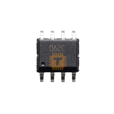
| Name | Original TL082 Dual JFET Op-Amp IC SOIC-8 |
| Code | IC0331 |
| Price | Rs.50.00 |
| In Stock | Yes |
| Package | SMD |
Product Details
The TL082 is a high-speed, dual JFET-input operational amplifier designed to offer a unique combination of high input impedance and low bias current. By integrating high-voltage JFETs and bipolar transistors on a single monolithic chip, it achieves high slew rates and low harmonic distortion, making it a favorite for high-fidelity audio pre-amplifiers and precision signal processing.
Specifications
- Supply Voltage: ±3V to ±18V (Dual Rail) or 6V to 36V (Single Rail)
- Slew Rate: 13V / us (Typical)
- Gain Bandwidth Product: 3MHz
- Input Bias Current: 30pA (Typical)
- Input Offset Voltage: 3mV (Typical)
- Low Harmonic Distortion: 0.003% (Typical)
- Package: SOIC-8 (Surface Mount)
Features
- High Input Impedance: The JFET input stage provides exceptionally low input bias and offset currents, which minimizes loading effects on high-impedance sensors.
- High Slew Rate: At 13V / us, the TL082 is capable of handling rapid signal changes without significant distortion, ideal for fast pulse processing.
- Internal Frequency Compensation: Simplifies circuit design by ensuring stability without the need for external compensation components.
- Latch-Up Free Operation: Designed to be robust against common op-amp latch-up issues.
- Output Short-Circuit Protection: Protects the IC from accidental damage during prototyping or maintenance.
Common Applications
- Audio Preamplifiers: Used in mixers and tone control circuits due to its low noise and high fidelity.
- Active Filters: Designing high-pass, low-pass, and band-pass filters with sharp roll-offs.
- Sample and Hold Circuits: Benefiting from the extremely low input bias current.
- High-Impedance Buffers: Interfacing high-impedance transducers (like piezo pickups) with standard electronics.
- Integrators and Differentiators: Precision mathematical signal processing.
Usage Tips
- Power Decoupling: For high-speed performance, place a 0.1uF ceramic capacitor between the V+ and V- pins as close to the IC as possible to reduce power supply noise.
- Input Voltage Range: Ensure the input signal stays within the specified common-mode input voltage range (typically 3V away from the supply rails) to avoid "phase reversal."
- SMD Soldering: As an SOIC-8 component, use fine-tip soldering equipment or solder paste with hot air. Ensure correct orientation by matching the "dot" or notch on the package with Pin 1 on the PCB.
- Single Supply Use: While optimized for dual supplies (e.g. ±12V), it can run on a single supply if the inputs are biased to half-supply (Vcc / 2).
Sharing is caring, show love and share the product with your friends.
Featured



Add to Cart