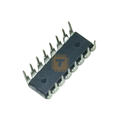
Original KA7500BD PWM Controller IC DIP-16 (IC0340) Products
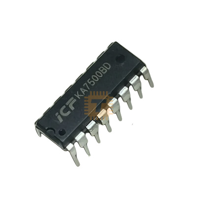
| Name | Original KA7500BD PWM Controller IC DIP-16 |
| Code | IC0340 |
| Price | Rs.60.00 |
| In Stock | Yes |
| Package | THT |
Product Details
The KA7500BD is a comprehensive fixed-frequency PWM control circuit containing all the functions required for the construction of switch-mode power supplies (SMPS). It is functionally equivalent to the industry-standard TL494. This IC is widely used in PC power supplies, DC-DC converters, and motor control systems due to its ability to drive two internal power transistors in either push-pull or single-ended configurations.
Specifications
- Supply Voltage (Vcc): 7V to 40V
- Output Current: 200mA (Collector Output Current)
- Oscillator Frequency: 1kHz to 300kHz
- Internal Reference Voltage: 5.0V (± 5%)
- Dead-Time Control Range: 0% to 100%
- Package: DIP-16 (Dual In-line Package)
Features
- Complete PWM Power Control Circuit: Includes an on-chip oscillator, two error amplifiers, a pulse-steering flip-flop, and an adjustable dead-time control.
- Uncommitted Output Transistors: The internal output transistors provide either common-emitter or emitter-follower output capability, offering flexibility for different circuit topologies.
- Output Control Pin: A dedicated pin allows for the selection of single-ended or push-pull operation.
- Precision Reference: Provides a stable 5V internal reference voltage to simplify external circuitry.
- Dead-Time Adjustment: Prevents "shoot-through" currents in push-pull configurations by providing a controllable dead-time between output pulses.
Common Applications
- ATX PC Power Supplies: Managing the primary voltage rails.
- DC-DC Buck/Boost Converters: Providing regulated power for industrial equipment.
- Inverters: Converting DC battery power to AC.
- Motor Speed Control: Utilizing PWM to efficiently control DC motor speed.
Usage Tips
- Oscillator Setup: The frequency is determined by the formula F = 1.1/Rt x Ct
- Output Mode: Connect the Output Ctrl (Pin 13) to REF (Pin 14) for push-pull operation, or to GND (Pin 7) for single-ended/parallel operation.
- Protection: Use the second error amplifier for over-voltage or over-current protection by comparing a sense voltage against the 5V reference.
- Heat Dissipation: While the IC handles the logic, ensure the external power MOSFETs or BJTs it drives are properly heatsinked for high-power applications.
Sharing is caring, show love and share the product with your friends.
Featured


Add to Cart