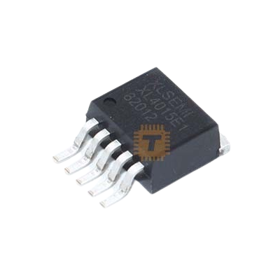
Original LP3669 Isolated Switching Power Supply Chip SOP-7 (IC0381) Products


| Name | Original LP3669 Isolated Switching Power Supply Chip SOP-7 |
| Code | IC0381 |
| Price | Rs.70.00 |
| In Stock | Yes |
Product Details
The Original LP3669 Isolated Switching Power Supply Chip SOP-7 is a high-performance, primary-side regulation (PSR) flyback offline SMPS controller IC designed for low-power AC-to-DC isolated power converters, wall chargers, and offline standby supplies. Featuring an integrated high-voltage power BJT/MOSFET within a compact SOP-7 package (with the missing 8th pin providing enhanced high-voltage creepage clearance), it eliminates the need for an external secondary-side optocoupler, TL431 reference shunt, and auxiliary feedback winding. Operating in continuous quasi-resonant (QR) pulse-frequency and pulse-amplitude modulation, the LP3669 delivers tight constant voltage (CV) and constant current (CC) regulation, ultra-low standby power consumption (<75mW>
Specifications
- Device Name / Part Number: LP3669 Series
- Topology: Isolated Flyback Converter with Primary-Side Regulation (PSR)
- Package Type: SOP-7 (Standard 8-pin footprint with Pin 6 removed for high-voltage isolation creepage)
- Integrated Power Switch: High-Voltage Power Transistor / BJT integrated on-chip
- Collector-to-Base / Drain Breakdown Voltage: ≥ 650 V to 800 V (Internal power switch rating)
- AC Input Line Range: Universal 85 V AC to 265 V AC (50/60 Hz)
- Continuous Output Power Rating:
- Enclosed Adapter (Universal 85–265V AC): Approx. 5.0 W to 12.0 W (variant dependent)
- Open-Frame / Peak Duty: Up to 15.0 W (with proper PCB thermal dissipation)
- Target Output Capability: Typically configured for 5V/1A, 5V/2A, or 12V/1A isolated DC rails
- Regulation Accuracy:
- Constant Voltage (CV) Precision: ±5?ross line and load variations
- Constant Current (CC) Precision: ±5?ross universal AC line voltage
- Standby Power Consumption: < 75>
- Control Modulation: Multi-Mode Quasi-Resonant (QR) PWM / PFM / Burst Mode
- Built-in Compensation: Built-in Line Compensation and Cable Drop Voltage Compensation
- Operating Supply Voltage (VCC): 8.0 V to 25.0 V DC (Internal self-startup circuitry)
- Protections:
- VCC Under-Voltage Lockout (UVLO) with hysteresis
- VCC Over-Voltage Protection (OVP)
- Output Short-Circuit Protection (SCP) with auto-restart hiccup mode
- Cycle-by-Cycle Primary Peak Current Limiting (OCP)
- Accurate Thermal Shutdown / Over-Temperature Protection (OTP)
- Operating Junction Temperature: -40°C to +150°C
- Net Weight: Approx. 0.15 g
Features
- Primary-Side Regulation (PSR) Architecture: Samples output voltage and current directly from the primary winding reflected wave, eliminating optocouplers, secondary reference ICs, and secondary bias networks to slash BOM costs.
- High-Voltage Safe SOP-7 Pinout: The physical removal of the high-voltage switch's adjacent pin (Pin 6 omitted) increases electrical creepage and clearance distances, preventing high-voltage arcing across humid PCB environments.
- Multi-Mode Quasi-Resonant (QR) Operation: Adjusts switching frequency and transitions during valley switching to minimize primary switch turn-on capacitive losses, improve efficiency, and lower EMI emissions.
- Integrated High-Voltage Power Switch: The internal monolithic switch eliminates external gate-drive circuits, minimizes ringing loops, and saves substantial board area on compact single-sided power PCBs.
- Internal Cable Drop Compensation: Built-in programmable/fixed line drop compensation offsets DC cable resistance, guaranteeing nominal 5V output at the end of long mobile charging cables.
Common Applications
- Mobile Phone & Tablet Wall Adapters: Cost-effective 5V 1A and 5V 2.1A USB wall bricks and plug-in travel adapters.
- Standby Auxiliary Power Supplies: Providing isolated auxiliary low-voltage rails (5V or 12V) for white goods, washing machines, refrigerators, and air conditioning motherboards.
- Smart Home & IoT Wall Plates: Compact AC-DC offline converter modules inside smart switches, WiFi wall plugs, and smart home relay boxes.
- Linear Regulator Replacements: Upgrading inefficient 50Hz/60Hz iron-core transformer adapters to high-efficiency offline SMPS circuits.
- Industrial Utility Metering: Low-power isolated power rails inside digital energy meters, environmental monitors, and sub-station sensor telemetry units.
Usage Tips
- High-Voltage Safety Precautions (CRITICAL):
- The primary side carries lethal rectified mains voltages (up to 375V DC across the bulk filter capacitor).
- Always power the prototype board through an isolated AC variac or mains isolation transformer during benchtop oscilloscope probing.
- Never connect standard earth-grounded oscilloscope probe ground clips directly to the primary bridge ground; doing so will trip building breakers and damage bench test equipment.
- Snubber Network Tuning (RCD Clamp):
- To protect the internal power switch from primary transformer leakage inductance spikes, install an optimized RCD clamp network (diode, resistor, and capacitor) across the transformer primary winding.
- Verify on an oscilloscope that the peak collector/drain turn-off voltage stays well within 80% of the internal switch's breakdown limit during maximum input AC voltage and full output load.
- PCB Layout & Creepage Clearances:
- Maintain at least 6.0 mm to 8.0 mm of isolation clearance (creepage) across the PCB isolation barrier separating primary high-voltage ground from secondary output ground.
- Keep the high-voltage switching loop (Bulk Capacitor (+) → Transformer Primary → IC Internal Switch → Current Sense Resistor → Bulk Capacitor (-)) as short and tightly routed as possible to suppress radiated EMI.
- Primary Current Sense Resistor (Rcs):
- The output constant current (CC) limit is determined directly by the external current-sense resistor connected between the CS pin and primary ground.
- Use a low-inductance, 1% metal film or precision surface-mount resistor for Rcs to ensure accurate current output calibration without thermal drift.
- Transformer Design & Winding Phase:
- Because PSR controllers detect the demagnetization interval and reflected voltage from the primary/auxiliary winding, transformer winding polarity (dot convention) is critical.
- Ensure the auxiliary winding voltage is strictly in-phase with the secondary output winding so that the feedback sampling network accurately tracks the output voltage profile.
Sharing is caring, show love and share the product with your friends.
Featured

Add to Cart

Add to Cart
Add to Cart

Other Products
Add to Cart