
REX-C700FK02 Dual Digital RKC Display PID Temperature Controller (MD1033) Products
| Name | REX-C700FK02 Dual Digital RKC Display PID Temperature Controller |
| Code | MD1033 |
| Price | Rs.4,250.00 |
| In Stock | Yes |
| Package | MODULE |
Product Details
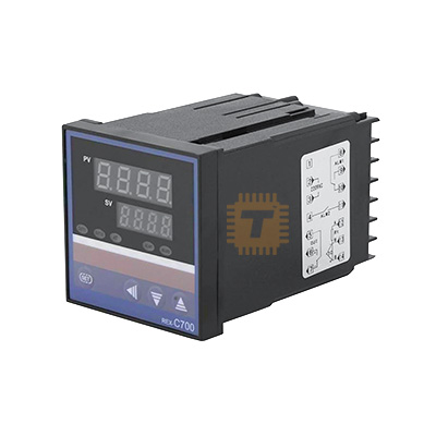
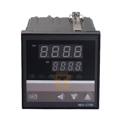
The REX-C700FK02 is an industrial-grade, intelligent dual-display PID (Proportional-Integral-Derivative) temperature controller developed under the classic RKC architecture design. Built into a highly visible 72mm x 72mm square panel footprint, this unit simultaneously references the Process Value (PV) and the Set Value (SV) via two independent digital LED windows. By leveraging advanced self-tuning PID algorithmic logic loops alongside multiple input sensor parameters, this device delivers highly stable, drift-free thermal regulations across demanding industrial process chambers.
Specification
- Model Suffix Coding Breakdown (
FK02):F: Predictive Intelligent PID control loop system with automatic self-tuning optimization capabilities.K: Default input type calibrated for standard K-Type Thermocouples.02: Designated operational range limit parameter (Default standard scale calibrated for 0℃ to 400℃).
- Panel Bezel Profile Dimensions: 72 x 72mm (Standard square panel cutout format)
- Dual Display Core: High-brightness 4-digit upper PV (Red LED) and lower SV (Green LED) arrays
- Configurable Input Types: K, J, R, S, B, E, T, N (Thermocouples) or Pt100 / Cu50 (RTD Platinum thermal probes)
- Primary Output Hardware Options:
- Mechanical Relay Contact (AC 250V / 3A resistive capacity)
- Voltage Pulse output (DC 0/12V logic to command external Solid State Relays - SSR)
- Alarm Outputs: 1x SPST Programmable Auxiliary Sub-Alarm Output relay line
- Main Operating Input Voltage: AC 100V to 240V (50/60 Hz auto-adaptive)
- Measurement Precision: ± 0.5% Full Scale value response rate
Features
- Intelligent Self-Tuning PID Algorithm: Avoids time-consuming manual parameter calculations. Activating the integrated auto-tune routine forces the controller to sample heat expansion profiles dynamically and calculate optimal proportional bands (P), integral constants (I), and derivative limits (D) to minimize temperature overshoot.
- Dual Simultaneous LED Data Tracking: Keeps operators constantly updated. The upper red numerical block reveals real-time sensor environment conditions (PV), while the lower green field mirrors your targeted processing setpoint (SV).
- High Barrier Anti-Interference Shell: Encased inside a heavy-duty, flame-retardant industrial chassis module. The internal motherboard incorporates deep noise-rejection filters capable of maintaining high measurement stability under harsh electrical interference fields.
- Flexible Sensor Calibration Profiles: Accommodates multi-probe systems. Via simple internal parameters accessed from the touch button panel, you can switch calibration profiles between different thermocouples or highly accurate Pt100 RTD elements without modifying hardware internals.
Common Applications
- Plastic Processing Equipment: Controlling precision heating zones on injection molding barrels, plastic extruders, and structural blow-molding frameworks.
- Industrial Kilns & Industrial Ovens: Managing uniform thermal environments inside high-heat ceramic kilns, metal tempering workstations, and continuous baking ovens.
- Packaging and Sealing Assemblies: Maintaining precise, constant thermal levels on plastic bag heat-sealing jaws, shrink-wrap tunnels, and vacuum pack hot-bars.
- Scientific Lab Incubators: Providing strict, drift-free ambient environment regulations inside chemical testing containers, biological incubators, and medical cleanrooms.
Professional Installation & Tuning Tips
- Configure Output Matching Correctly: Before wiring up the load, look closely at the device label on the side of your specific model sub-variant. Units configured for Relay Output expect low-power contacts directly switching the coil of an external AC contactor. Units configured for SSR Output send a 12V DC pulse train designed to command Solid State Relays. Hooking an AC main load directly to a low-voltage SSR logic control pin will instantly destroy the controller's internal circuitry.
- Run a Dedicated Auto-Tune Routine: Upon initial machine power-up or whenever you exchange the heating elements, load your target operating temperature value onto the SV display window and initiate the Auto-Tune (AT) function. The display will blink during the loop computation cycle as it fires the heater through test iterations. Let it complete the processing loop completely undisturbed until the blinking stops to ensure highly accurate, overshoot-free operation.
- Isolate High-Power Sensor Traces: Never route your low-voltage thermocouple or Pt100 signal wires inside the same metal conduit or wiring harness running heavy three-phase AC power lines to motors or heating elements. Electromagnetic induction will bleed high-frequency line noise into the measurement path, causing the PV screen to flicker erratically or report false "uuu" open-circuit faults.
- Compensate for Sensor Positioning Offsets: If your structural thermocouple probe is mounted deep inside the metal framework away from the actual product processing zone, there will be a minor physical thermal delay. Leverage the internal Sensor Correction (SC) parameter menu layout to dial in an offset value, allowing the PV line to match the actual true heat index of your processing work area.
Sharing is caring, show love and share the product with your friends.
Featured

Add to Cart


Add to Cart

Add to Cart
Other Products
Add to Cart

Add to Cart
