RS232 Serial to TTL Converter Module MAX3232 Dual Row (MD1030) Products

| Name | RS232 Serial to TTL Converter Module MAX3232 Dual Row |
| Code | MD1030 |
| Price | Rs.450.00 |
| In Stock | Yes |
| Package | MODULE |
Product Details
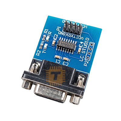
The MAX3232 RS232 to TTL Converter Module is a bidirectional level shifter engineered to bridge the communication gap between legacy RS232 serial ports (which operate at ± 12V) and modern microcontroller UART ports (which operate at 3.3V or 5V TTL logic). This specialized Dual Row variant features an ultra-compact footprint with mirrored or parallel dual-row pin configurations, making it incredibly easy to embed directly into tight enclosures, breadboards, or custom PCB headers.
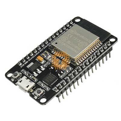
Unlike the older MAX232, the onboard MAX3232 IC supports true low-voltage systems, allowing you to interface directly with both 3.3V devices (like ESP32 and Raspberry Pi) and 5V devices (like Arduino Uno) without needing separate logic level shifters.
Technical Specifications
- Converter Chip: MAX3232 (or SP3232 alternative)
- Protocol: RS232 Asynchronous Serial
- Operating Voltage: 3.0V to 5.5V DC
- Logic Level Support: Fully compatible with 3.3V and 5V systems
- Max Baud Rate: Up to 250 kbps (typical guaranteed 120 kbps)
- Channels: Dual Transmitters & Dual Receivers (Full Duplex)
- Operating Current: Approx 8mA
- Pin Spacing: Standard 2.54mm (0.1 inch) pitch, Dual-Row layout
Features
- Wide Voltage Versatility: Eliminates the risk of logic level mismatch. It automatically scales its translated outputs based on the Vcc voltage supplied by your host microcontroller.
- Dual Transceiver Capacity: Contains two independent driver/receiver channels, allowing you to run a full hardware-flow-control serial bus (TX, RX, CTS, RTS) or run two distinct TX/RX serial lines simultaneously.
- On-Chip Charge Pump: Uses four tiny onboard surface-mount capacitors to multiply low input voltages into the higher positive and negative voltage rails required by RS232 lines.
- High ESD Protection: Protects sensitive microcontroller pins from standard electrostatic discharges often encountered when plugging and unplugging rugged serial data cables.
- Hardware Recovery Utility: Widely used as a "brush board" tool to flash firmware, unbrick routers, or extract diagnostic boot logs from home appliances and hard drives.
Pin Configuration (Dual-Row Layout)
The module breaks out the pins into a convenient dual-row format, typically separating the TTL Logic side from the RS232 High-Voltage side:
TTL Side (To Microcontroller / UART)
- VCC: Power Supply Input (3.3V or 5V). Matches your MCU's logic level.
- GND: Common system ground.
- TXD / TTL-TX: Connects to the Transmit pin of your microcontroller's UART.
- RXD / TTL-RX: Connects to the Receive pin of your microcontroller's UART.
RS232 Side (To PC COM Port / Legacy Device)
- VCC / +: Secondary or pass-through power rail.
- GND / -: Secondary system ground.
- RS232-TX: The high-voltage output signal heading to the remote RS232 device.
- RS232-RX: The high-voltage input signal coming from the remote RS232 device.
Common Applications
- Firmware Flashing & Upgrades: Upgrading software or fixing corrupted firmware on routers, satellite set-top boxes, and automotive infotainment systems.
- Industrial Interfacing: Connecting modern IoT gateways to vintage PLCs, CNC machines, barcode scanners, and scientific instruments using traditional DB9 connectors.
- Legacy Peripheral Control: Allowing microcontrollers to communicate with older GPS receivers, external dial-up modems, or POS receipt printers.
- PC-to-MCU Debugging: Directly piping raw serial data from an industrial computer's physical serial COM port down into a development circuit board.
Usage & Installation Tips
- Rx/Tx Crossover Rules: When wiring the TTL side to your microcontroller, remember to map TXD to RX and RXD to TX. However, check your specific module markings; some breakout boards pre-cross the traces for convenience.
- Match the Voltage Supply: If you are connecting the module to an ESP32 or Raspberry Pi, power the module's Vcc pin with 3.3V. If you power it with 5V while hooked to a 3.3V processor, the RX line will output 5V spikes that can burn out the microcontroller's GPIO pin.
- Keep High-Voltage Lines Insulated: The RS232 side runs at native serial voltages up to ± 12V – ± 15V. Ensure these traces do not accidentally touch adjacent lower-voltage digital sensor pins on your breadboard.
- Verify Cable Continuity: RS232 devices can be configured as DTE (Data Terminal Equipment) or DCE (Data Circuit-terminating Equipment). If communication fails despite correct logic wiring, you may need a Null Modem adapter or swapped TX/RX lines on the RS232 side.
Sharing is caring, show love and share the product with your friends.
Featured
Add to Cart

Add to Cart


