STM32F103C8T6 STM32 ARM Minimum System Development Board Blue Pill (DB0043) Products

We are sorry but the product is out of stock, please check back after few days.
| Name | STM32F103C8T6 STM32 ARM Minimum System Development Board Blue Pill |
| Code | DB0043 |
| Price | Rs.600.00 |
| In Stock | No |
| Package | MODULE |
Product Details
If this product is out of stock, you may consider buying the HK32F103C8T6 HK32 ARM Minimum System Development Board Blue Pill (STM32F103C8T6 Clone) which is a compatible clone.
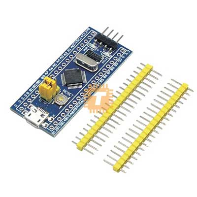
The STM32F103C8T6, commonly known as the "Blue Pill," is a high-performance, low-power development board based on the ARM Cortex-M3 32-bit core. It is a powerful and affordable alternative to 8-bit microcontrollers, offering significantly more processing power, memory, and peripheral options for complex embedded projects.
Specifications
- Core: ARM 32-bit Cortex-M3 CPU.
- Clock Speed: 72MHz maximum frequency.
- Memory: 64KB Flash memory and 20KB SRAM.
- Operating Voltage: 2.0V to 3.6V DC (Onboard 3.3V regulator included).
- I/O Pins: 37 GPIO pins (most are 5V tolerant).
- Timers: 3 General-purpose timers and 1 Advanced-control timer.
- Communication: 2x I2C, 2x SPI, 3x USART, 1x USB 2.0 Full Speed, and 1x CAN 2.0B.
- ADC: 2x 12-bit Analog-to-Digital Converters (up to 10 channels).
- Debug Mode: Serial Wire Debug (SWD) interface.
Features
- Processing Power: The 32-bit architecture and 72MHz clock speed allow it to handle tasks like real-time motor control or complex math far better than standard 8-bit boards.
- USB Support: Features an onboard Micro-USB connector for power and communication (requires a bootloader for direct programming via USB).
- Onboard RTC: Includes a built-in Real-Time Clock (RTC) with a dedicated battery pin (VBAT) for time-keeping applications.
- Compact Form Factor: The "DIP" style pinout allows it to be plugged directly into a breadboard for rapid prototyping.
- Jumpers for Boot Selection: Two onboard jumpers (BOOT0 and BOOT1) allow you to switch between Flash, System Memory, or SRAM boot modes.
Pin and Header Guide
- V3 / GND: 3.3V Power and Ground.
- 5V: 5V Input (regulated down to 3.3V for the chip).
- B0+ / B1-: Boot mode selection jumpers.
- SWDIO / SWCLK: Pins used for programming and debugging via an ST-Link V2.
- PA0–PA15 / PB0–PB15: General Purpose I/O pins with alternate functions like PWM, ADC, and SPI.
- Reset Button: Onboard button to manually restart the microcontroller.
Common Applications
- Robotics: Controlling multiple servos and high-speed motor drivers.
- IoT Gateways: Handling data from various sensors and communicating via WiFi or LoRa modules.
- Industrial Automation: Interfacing with CAN bus systems and high-speed data logging.
- USB Peripherals: Creating custom HID devices like keyboards or joysticks.
Usage Tips
- Programming: Unlike Arduino, the Blue Pill is typically programmed using an ST-Link V2 programmer via the 4-pin SWD header. It can also be programmed via Serial (UART1) using a USB-to-TTL adapter.
- USB Port Usage: In many versions, the Micro-USB port is only for power and serial communication by default. To upload code directly through this port, you must first flash a "STM32duino" bootloader.
- Powering the Board: Always ensure you are providing a stable 5V to the 5V pin or 3.3V to the 3.3V pin. Do not apply 5V directly to the 3.3V pin as it will damage the MCU.
- 5V Tolerance: While the MCU is 3.3V, many of the I/O pins are "5V tolerant," meaning they can safely read 5V digital signals without a level shifter. Check the pinout map for specific markings.
Sharing is caring, show love and share the product with your friends.
Featured

Add to Cart


Add to Cart
Add to Cart
Other Products


Add to Cart
