
TCS3200 Colour Recognition Sensor Module for Arduino (MD1056) Products
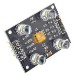
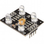
| Name | TCS3200 Colour Recognition Sensor Module for Arduino |
| Code | MD1056 |
| Price | Rs.1,150.00 |
| In Stock | Yes |
| Package | MODULE |
Product Details
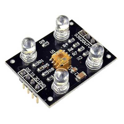
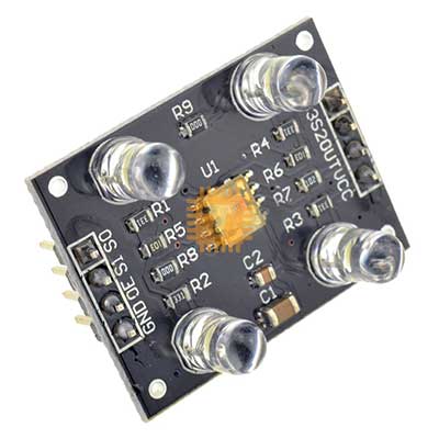
The TCS3200 Colour Recognition Sensor Module for Arduino is an optical color detection sensor board engineered for high-accuracy surface color identification, industrial sorting automation, ambient light analysis, and educational robotics. Built around the TAOS TCS3200 programmable color light-to-frequency converter IC, it integrates an 8×8 photodiode array (16 red-filtered, 16 green-filtered, 16 blue-filtered, and 16 clear photodiodes) that converts light intensity directly into a square-wave frequency output with a 50% duty cycle. The output frequency is directly proportional to radiant light intensity, enabling direct digital interfacing with microcontroller GPIO timer/counter pins without requiring an external analog-to-digital converter (ADC). Equipped with four onboard bright white spotlight LEDs to provide controlled, uniform surface illumination, it is a standard sensor solution for Arduino, ESP32, and Raspberry Pi color-sorting systems.
Specifications
- Sensor IC: TAOS TCS3200 (Programmable Color Light-to-Frequency Converter)
- Operating Supply Voltage (VCC): 2.7 V to 5.5 V DC (Nominal: 5.0 V DC)
- Operating Supply Current (ICC): Approx. 15 mA to 20 mA (Illumination LEDs Active)
- Photodiode Array: 8 × 8 Matrix Configuration (Total 64 Silicon Photodiodes)
- 16 Photodiodes with Red Optical Filters (λpeak ≈ 640 nm)
- 16 Photodiodes with Green Optical Filters (λpeak ≈ 524 nm)
- 16 Photodiodes with Blue Optical Filters (λpeak ≈ 470 nm)
- 16 Photodiodes with Clear / Non-Filtered Response (Total White / IR Intensity)
- Output Signal Type: Digital Square Wave (50% Duty Cycle) with frequency proportional to light irradiance
- Full-Scale Output Frequency (fO): 500 kHz (Typical at 100% scaling, Ee = 130 μW/cm²)
- Programmable Output Frequency Scaling (S0, S1 Pins):
- Power Down Mode (0%): Standby / Off
- 2% Frequency Scaling: Matches slower microcontrollers (e.g., ATmega328P / Arduino UNO)
- 20% Frequency Scaling: Balanced speed/resolution mode
- 100% Frequency Scaling: High-speed microcontrollers / DSPs (ESP32, STM32)
- Color Filter Selection Logic (S2, S3 Pins):
- S2 = LOW, S3 = LOW: Red Filter Active
- S2 = LOW, S3 = HIGH: Blue Filter Active
- S2 = HIGH, S3 = LOW: Clear / No Filter Active
- S2 = HIGH, S3 = HIGH: Green Filter Active
- Integrated Illumination: 4 × 5mm High-Brightness Pure White SMD/Through-Hole Spotlight LEDs
- LED Control Interface: Dedicated LED pin (Active HIGH / LOW control to toggle illumination LEDs on or off)
- Nonlinearity Error: ≤ 0.2% at 50 kHz
- Temperature Coefficient: ±200 ppm/°C
- Optimal Detection Distance: Approx. 10 mm to 15 mm (0.39" to 0.59" from target object)
- Operating Ambient Temperature Range: -40°C to +85°C
- Module Dimensions: Approx. 33 mm × 25 mm × 20 mm (L × W × H)
- Net Weight: Approx. 8.0 g to 10.0 g
Pinout & Terminal Definition
- VCC: Positive Power Supply Input (+2.7 V to +5.5 V DC, typically +5.0 V)
- GND: Ground Reference Connection (0 V)
- S0, S1: Output Frequency Scaling Selection Inputs (Selects 0%, 2%, 20%, or 100% output multiplier)
- S2, S3: Color Filter Selection Inputs (Selects Red, Green, Blue, or Clear photodiode sets)
- OUT: Digital Square Wave Frequency Output (Connects directly to microcontroller interrupt or timer pin)
- OE (Output Enable) / LED: Active-LOW Output Enable / High-impedance tri-state pin (or LED on/off toggle pin on breakout boards)
Features
- Direct Digital Frequency Output: Converts optical radiant energy into a digital square-wave frequency, allowing direct connection to digital GPIO pins without requiring external analog circuits, op-amps, or ADC converters.
- Even Multi-Point Photodiode Matrix: Distributes 64 silicon photodiodes across an interdigitated grid pattern to eliminate spatial alignment errors and ensure uniform spectral sensitivity across uneven target surfaces.
- Onboard Target Illumination: Four bright white LEDs illuminate the scanned surface, creating a controlled, stable reflection environment that minimizes readings drift from changing room ambient lighting.
- Programmable Frequency Prescaler: Hardware-selectable output scaling (2%, 20%, 100%) prevents counter overflow on lower-speed 8-bit microcontrollers (Arduino UNO) while supporting high-speed 32-bit MCUs (ESP32).
- High Dynamic Range & Non-Linearity Compensation: Broad dynamic sensing range allows fine discrimination between subtle shades, tints, and surface finishes across the visible light spectrum.
Common Applications
- Industrial Sorting Automation: Automated color inspection and sorting of manufactured parts, colored pills, food produce, and packaging on conveyor belts.
- Robotics & Navigation: Color-coded line-following robots, autonomous grid navigation, and target acquisition markers for competition arenas.
- Textile & Paint Matching: Portable colorimeters, surface paint matching tools, fabric dye consistency checkers, and printing ink quality testing.
- STEM & Educational Projects: Laboratory colorimeters, RGB color mixers, chemistry titration endpoint indicators, and interactive student learning exhibits.
- Ambient Light & Color Temperature Analysis: Environmental light spectrum sensing and monitor calibration fixtures.
Usage Tips
- Frequency Scaling Selection for Arduino (CRITICAL):
- The full-scale output of the TCS3200 reaches up to 500 kHz. An 8-bit Arduino UNO running at 16 MHz struggles to sample pulse intervals accurately above 100 kHz using standard software functions.
- For Arduino UNO / Nano (ATmega328P), set the module to 20% frequency scaling by setting S0 = HIGH and S1 = LOW.
- For ultra-low power or slower clock microcontrollers, configure for 2% scaling (S0 = LOW, S1 = HIGH). For high-speed 32-bit controllers (ESP32, STM32, Teensy 4.0), set 100% scaling (S0 = HIGH, S1 = HIGH) for maximum sampling resolution.
- Optical Distance & Shroud Enclosure:
- Maintain the sensor at a fixed distance of 10 mm to 15 mm from the target surface for consistent color reading.
- Ambient room lights (fluorescent tubes, sunlight, AC flicker) introduce significant noise. Enclose the sensor and target within an opaque dark shroud or 3D-printed black hood to block stray light.
- White Balance Calibration Routine:
- Before running color recognition algorithms, perform a two-point calibration:
- White Calibration: Place a matte pure white card 10 mm in front of the illuminated sensor, cycle through S2/S3 to measure the baseline frequencies for Red (fR), Green (fG), and Blue (fB), and map these values to 255.
- Black Calibration: Point the sensor into an open dark chamber or against a matte black surface to record the zero-floor frequencies, mapping them to 0.
- Measurement Technique in Code: Measure the output frequency on the OUT pin using either the pulse In function (measuring pulse width / half-period in microseconds) or an external hardware timer input interrupt (counting pulses over a fixed 50 ms–100 ms time window) for higher accuracy and non-blocking performance.
- Filter Settling Delay: When toggling the S2 and S3 filter select pins, allow a brief delay of at least 2 ms to 5 ms in your firmware before measuring the pulse on the OUT pin to allow the internal photodiode switching transients to stabilize.
Sharing is caring, show love and share the product with your friends.
Featured


Add to Cart

Add to Cart
Other Products
Add to Cart

Add to Cart
Add to Cart
