Vero Board Dot Epoxy FR4 6x8cm (TA1819) Products
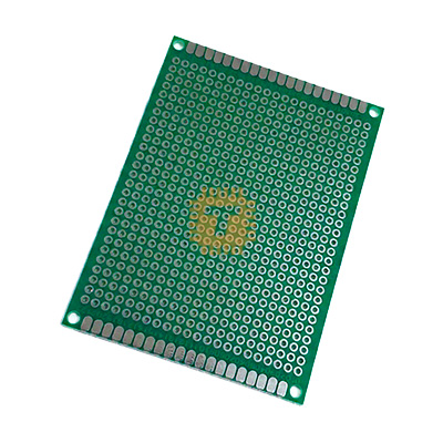
| Name | Vero Board Dot Epoxy FR4 6x8cm |
| Code | TA1819 |
| Price | Rs.100.00 |
| In Stock | Yes |
| Package | ACC |
Product Details
The Vero Board Dot Epoxy FR4 6x8cm is an industrial-grade, Single sided prototyping circuit board engineered for high-reliability electronics assembly, permanent hardware prototyping, and custom circuit design. Manufactured from military-standard FR4 glass-reinforced epoxy laminate, it delivers superior mechanical stiffness, flame resistance, and thermal endurance compared to low-cost paper-phenolic (bakelite) stripboards. Featuring a standard 2.54 mm (0.1") grid of individual through-hole plated (PTH) circular solder dots with tinned annular rings, it provides high electrical isolation and pad adhesion, making it ideal for point-to-point wiring, microcontrollers, discrete analog circuits, and high-vibration robotics applications.
Specifications
- Board Type: Universal Prototype Matrix Board (Dot Perfboard / Vero Board)
- Base Substrate Material: High-Quality FR4 Glass-Fiber Reinforced Epoxy Laminate
- Flammability Rating: UL94V-0 Flame Retardant
- Board Outline Dimensions: 60.0 mm × 80.0 mm (6 × 8 cm / ~2.36" × 3.15")
- Substrate Thickness: Standard 1.6 mm (±0.1 mm rigid profile)
- Grid Pattern / Pitch: Standard 2.54 mm (0.100 Inches / 100 mil) center-to-center pitch
- Matrix Layout: Individual isolated round solder dots
- Hole Diameter: Approx. 1.0 mm (Accommodates standard DIP IC leads, 20–24 AWG wire, and terminal headers)
- Hole Count: Approx. 22 × 30 holes (660 through-plated tie points)
- Plating / Finish: High-Purity HASL (Hot Air Solder Leveling) Lead-Free or Tin-Plated Copper
- Through-Hole Plating: Full barrel copper plating interconnecting top and bottom annular rings
- Corner Mounting Holes: 4 × Pre-drilled corner mounting holes (~3.0 mm to 3.2 mm diameter for M3 standoffs)
- Dielectric Breakdown Voltage: ≥ 30 kV/mm
- Insulation Resistance: ≥ 1.0 × 10¹² Ω
- Operating Temperature Envelope: -40°C to +130°C (Tg ≥ 130°C to 140°C)
- Net Weight: Approx. 14.5 g to 16.0 g
Features
- High-Strength FR4 Substrate: Unlike brittle phenolic paper boards, this woven glass-epoxy matrix resists cracking, bending, and warping under mechanical stress and vibration.
- Plated-Through-Hole (PTH) Architecture: Copper barrels sleeve every hole, bonding the top and bottom circular pads together; this eliminates lifted pads caused by prolonged soldering iron contact or component rework.
- Independent Isolated Dot Matrix: Every solder pad is electrically isolated from adjacent pads, providing complete circuit flexibility for point-to-point enameled jumper routing without requiring copper strip cutting.
- Pre-Tinned Solder Rings: Solder pads are coated with smooth, oxidation-resistant tin plating that accepts leaded and lead-free solder immediately with rapid wetting and minimal flux splatter.
- Dedicated Corner Mounting Holes: Four symmetrically positioned M3-compatible corner holes allow secure mounting inside project boxes, metal chassis, or 3D-printed enclosures using standard standoffs.
Common Applications
- Permanent Prototype Assembly: Transferring tested solderless breadboard circuits into durable, permanent soldered hardware modules for industrial and field deployment.
- Microcontroller Carrier Boards: Building custom break-out motherboards for Arduino Nano, ESP32 DevKit, STM32 BlackPill, or Raspberry Pi Pico platforms.
- Analog & Power Circuit Prototyping: Assembling linear voltage regulators, op-amp signal conditioners, discrete transistor amplifiers, and audio preamps.
- Robotics & Drone Control Nodes: Hand-wiring custom sensor hubs, power distribution blocks, and relay drive boards subjected to continuous mechanical vibration.
- Educational STEM & University Labs: Hands-on electronics soldering training, student laboratory practicals, and engineering capstone projects.
Usage Tips
- Point-to-Point Wiring Technique:
- Because each hole is an electrically isolated island, create circuit traces using 30 AWG Kynar wire-wrap wire, fine enameled magnet wire, or bare tinned copper bus wire routed along the underside.
- Alternatively, bend component lead tails flush against adjacent pads and bridge them with a bead of solder to form short, low-resistance power busses.
- Soldering Temperature & Pad Protection:
- Set your soldering iron tip to 320°C to 350°C (608°F to 662°F).
- Although FR4 PTH pads resist heat significantly better than single-sided paper boards, avoid holding the iron tip on a single pad for more than 3 to 4 seconds to maintain substrate bonding integrity.
- Cutting & Sizing:
- If you need to resize the board, use a carbide PCB guillotine, metal shear, or high-speed rotary cutoff wheel with proper dust extraction.
- Do not attempt to score and snap FR4 boards with a standard utility knife; the woven glass fibers will splinter, leaving rough, hazardous edges. Always wear an N95 dust mask when cutting or sanding fiberglass.
- Mounting & Clearance:
- Use nylon or brass M3 standoffs (minimum 6 mm height) beneath the four corner mounting holes.
- Ensure the underside solder points do not contact metal enclosure panels, chassis plates, or battery covers to avoid catastrophic electrical shorts.
- Cleaning Flux Residue: After finishing all solder joints, scrub the board using a stiff ESD brush soaked in Isopropyl Alcohol (IPA ≥ 99%) to remove sticky rosin residue, leaving a professional, transparent finish.
Sharing is caring, show love and share the product with your friends.
Featured

Add to Cart

Add to Cart

Other Products
Add to Cart
Add to Cart