LED Bar Graph Display 4 Colour 10 Segment Red Yellow Green Blue (RRYYYGGGGB) KYX-B10BGYR (DM0035) Products

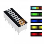
| Name | LED Bar Graph Display 4 Colour 10 Segment Red Yellow Green Blue (RRYYYGGGGB) KYX-B10BGYR |
| Code | DM0035 |
| Price | Rs.140.00 |
| In Stock | Yes |
| Package | THT |
Product Details
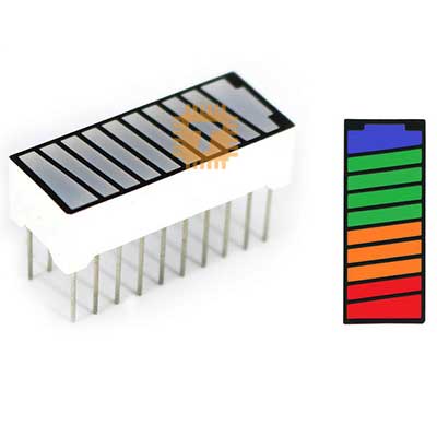
The KYX-B10BGYR is a 10-segment multi-colour LED bar graph display featuring a progressive four-colour visual layout: 1 Blue, 4 Green, 3 Yellow, and 2 Red segments. Packaged in a compact, industry-standard 20-pin dual in-line package (DIP), it provides a clear, high-contrast visual readout for progressive level monitoring. It is widely used to display battery charge states, audio VU levels, liquid volumes, signal strength, and alarm thresholds in industrial control and consumer electronics.
Specifications
- Model: KYX-B10BGYR
- Display Type: 10-Segment LED Bar Graph
- Segment Colour Sequence: 1 Blue, 4 Green, 3 Yellow, 2 Red (B-G-G-G-G-Y-Y-Y-R-R)
- Package Style: 20-Pin Dual In-line Package (DIP-20)
- Pin Pitch: 2.54 mm (Standard breadboard and perfboard spacing)
- Forward Current per Segment: 15mA to 20mA (Nominal), 30mA (Peak max)
- Forward Voltage Drops (Typical at 20mA):
- Red: 1.8V to 2.2V
- Yellow: 2.0V to 2.4V
- Green: 2.1V to 2.4V (or 3.0V to 3.2V for true-green variants)
- Blue: 3.0V to 3.3V
- Reverse Voltage Max: 5V
- Operating Temperature: -25°C to +85°C
- Surface / Segment Finish: Black faceplate with white diffused segment windows for optimal off/on contrast
Interface and Pinout Guide
The module contains 10 isolated LED elements mapped across 20 pins, allowing either Common Anode, Common Cathode, or individual control depending on circuit wiring:
- Pin Rows: 2 parallel rows of 10 pins spaced 7.62 mm (0.3 inches) apart.
- Segment 1 (Blue): Anode Pin 1 / Cathode Pin 20
- Segment 2 (Green): Anode Pin 2 / Cathode Pin 19
- Segment 3 (Green): Anode Pin 3 / Cathode Pin 18
- Segment 4 (Green): Anode Pin 4 / Cathode Pin 17
- Segment 5 (Green): Anode Pin 5 / Cathode Pin 16
- Segment 6 (Yellow): Anode Pin 6 / Cathode Pin 15
- Segment 7 (Yellow): Anode Pin 7 / Cathode Pin 14
- Segment 8 (Yellow): Anode Pin 8 / Cathode Pin 13
- Segment 9 (Red): Anode Pin 9 / Cathode Pin 12
- Segment 10 (Red): Anode Pin 10 / Cathode Pin 11
(Note: Polarity can be reversed simply by rotating the package or alternating anode/cathode connections, as segments are electrically independent).
Key Features
- Intuitive Multi-Colour Gradient: The progressive Blue-Green-Yellow-Red layout instantly communicates status thresholds: Blue for power/standby, Green for safe/normal, Yellow for warning, and Red for critical/maximum levels.
- Electrically Isolated Segments: Each segment's anode and cathode are brought out to independent pins, eliminating shared bus restrictions and supporting multiplexing, shift registers, or dedicated driver ICs.
- High Contrast and Uniform Diffusion: Built with a dark faceplate and uniform light diffusion to eliminate bleed-through between neighboring bars.
- Breadboard and PCB Friendly: Features standard 2.54 mm pin spacing that slots directly into solderless breadboards, IC sockets, or standard PCB layouts.
Common Applications
- Audio Equipment: Peak-level indicators, graphic equalizers, and VU meters.
- Battery Management Systems (BMS): Visual state-of-charge (SoC) gauges for battery packs and portable tools.
- Industrial Process Control: Visual monitoring for pressure, temperature, flow rate, and liquid storage levels.
- Security & Warning Systems: Progressive hazard proximity indicators and alarm thresholds.
Usage Tips
- Current Limiting Resistors: Never drive segments directly from a fixed voltage rail without current-limiting resistors. Because Blue, Green, Yellow, and Red have differing forward voltages, calculate distinct resistor values (or use 220 to 470 ohm resistors per pin) to achieve balanced brightness across all colours.
- Driver IC Compatibility: Directly compatible with display driver ICs like the LM3914 (linear display), LM3915 (logarithmic display), LM3916 (VU scale), 74HC595 shift registers, or direct microcontroller GPIO pins.
- Breadboard Orientation: Check segment polarity with a multimeter in diode-test mode before soldering to ensure the Blue end aligns with the intended lower/starting pin assignment of your schematic.
Sharing is caring, show love and share the product with your friends.
Featured

Add to Cart


Add to Cart

Add to Cart