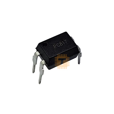
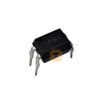
Original PC817 Optocoupler IC DIP-4 (IC0341) Products
We are sorry but the product is out of stock, please check back after few days.
| Name | Original PC817 Optocoupler IC DIP-4 |
| Code | IC0341 |
| Price | Rs.50.00 |
| In Stock | No |
| Package | THT |
Product Details
The PC817 is a widely used 4-pin optocoupler (also known as an opto-isolator). It consists of an infrared emitting diode (IRED) optically coupled to a phototransistor. Its primary function is to provide electrical isolation between two circuits, allowing a low-voltage signal to control a higher-voltage circuit without any physical electrical connection, which protects sensitive components from high-voltage spikes and noise.
Specifications
- Isolation Voltage (Viso): 5.0kV (RMS) — Provides a strong safety barrier.
- Collector-Emitter Voltage (Vceo): Up to 80V.
- Forward Current (IF): 50mA (Maximum continuous).
- Collector Current (IC): 50mA (Maximum).
- Current Transfer Ratio (CTR): 50% To 600% (varies by rank/binning).
- Response Time (tr): 4us (Typical) - Suitable for low-to-medium speed switching.
- Package: DIP-4 (Through-hole).
- Galvanic Isolation: Physically separates input and output stages to prevent ground loops and protect microcontrollers from power surges.
- High Noise Immunity: Excellent at suppressing common-mode noise between circuits.
- High CTR: Efficiently transfers signals even with low input currents.
- Compact Footprint: Simple 4-pin design makes it easy to integrate into both breadboards and permanent PCBs.
- Switch Mode Power Supplies (SMPS): Providing feedback from the output side to the control side while maintaining safety isolation.
- Microcontroller Interfaces: Controlling relays, motors, or solenoids from a 3.3V or 5V digital pin.
- Logic Ground Isolation: Separating digital ground from noisy power ground in industrial environments.
- Signal Transmission: Passing data between systems operating at different voltage potentials.
- Input Resistor: Always include a series resistor with the input (Pin 1) to limit the current through the IR LED. For a 5V logic signal, a 220 Ohm to 470 Ohm resistor is typical.
- Output Switching: Since the output is a transistor, you generally need a pull-up resistor on the Collector (Pin 4) if you want to read a logic signal on the output side.
- Orientation: Look for the small "dot" or notch on the package body; this indicates Pin 1 (Anode).
- Speed Limits: While great for DC switching and low-speed signals (like PWM or status signals), it may struggle with high-speed data protocols like high-speed SPI or I2C.
Sharing is caring, show love and share the product with your friends.
Featured

Add to Cart
Add to Cart

Other Products
Add to Cart